2025 EC Rollercoaster Cart:
In 2025 I was responsible for the cart for the rollercoaster. Over the summer, I designed the entire thing, and carried out a number of finite-element analyses to prove that it would hold up to rollercoaster operation with a sufficient factor of safety. Since I was not on campus, the fabrication of the cart was carried out by other students based on my plans.
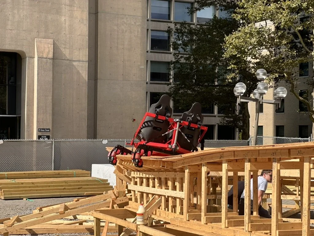
The cart is a passive mechanism which constrains the riders to the track and allows them to travel down it in a safe, controlled fashion. The energy required to move the cart along the track is solely provided by gravitational potential from starting the coaster at the top of a tower. Electrically powered motion is never used since that incurs amusement park regulations.
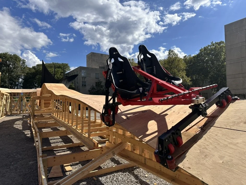
The structure of the cart is primarily constructed from welded steel tubing, and the seats are FIA approved racing seats with a 5 point harness.
I was responsible for the rollercoaster in 2022 as well, but we reused a previous year’s cart design. That cart weighed 250lb because it was made from wood, which has a poor strength-to-weight ratio but is easy to work with. It was problematic since our coasters are gravity powered, meaning we had to haul this heavy object up the 3 story tower for each rider.
My new cart weighs 200lb, is stronger and seats 2 people. This halves the number of resets and each reset is less work. Additionally, the frame is much stronger, and includes more articulation joints so the cart can travel around banked turns, twisting tracks, etc.

3D Model:
Structural Analysis:
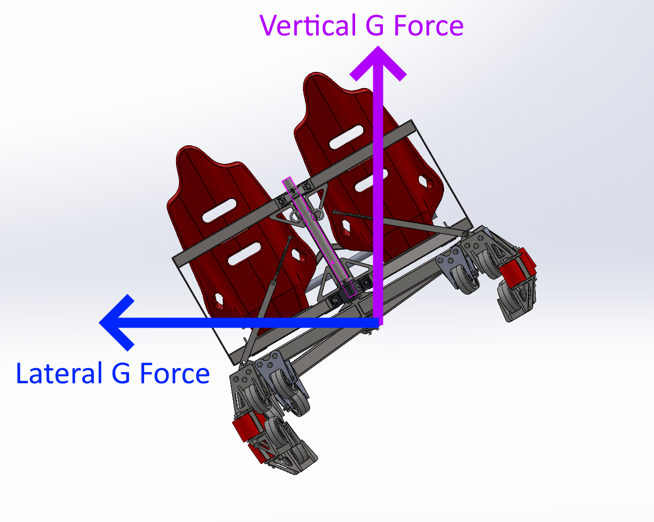
To conduct the structural analysis on the cart, my friends who designed the rollercoaster structure simulated the path the cart would take traveling down the track, yielding maximum G forces in the vertical and lateral directions aligned with the world reference frame.


This allowed me to calculate the maximum vertical force, lateral force and shear force on the track. I tried to use overestimates for the force wherever possible to be conservative. The mass of the cart is 200lbs, and the riders were assumed to also be 200lbs each. (We imposed a rule that the rider’s weight must add to less than 400lb during the coaster operation).
Vertical Force: 2.9G * (200+200*2) = 1740 lbf
Lateral Force: 1.7G * (200+200*2) = 850 lbf
The lateral force was not very useful for cart calculations because it occurs on banked turns but is aligned to the world reference frame (parallel to the ground). This force was instead used to evaluate the side-to-side stability of the wooden track structure. In order to back calculate the actual shear force on the cart (pink in the diagram below) I would have to take into account how much the cart is tilting at each point that the lateral force was simulated and project the force according to that, which would be complicated.
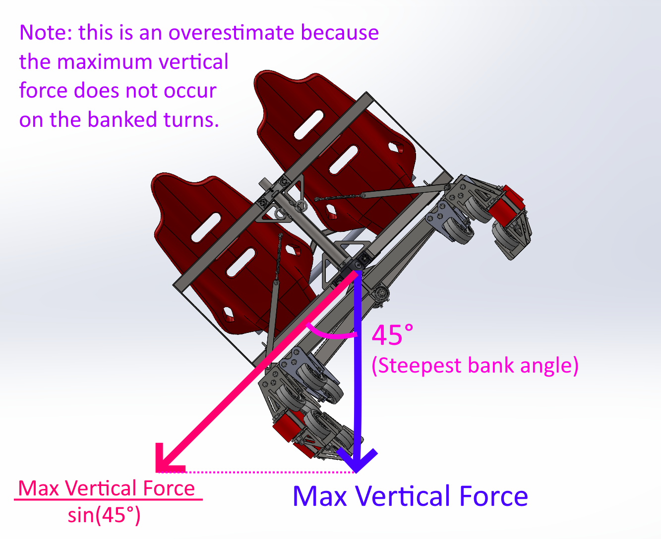
Shear Force: 1740 / sin(45°) = 2460 lbf
Instead, for the shear force I decided to instead project the maximum vertical force onto the steepest angle that the cart tilts during the banked turns for a generous overestimate.
The first thing I analyzed was the main frame of the cart. It is made of a steel box tubing, holds the seats, and surrounds the riders. This year, we have upgraded our cart to be constructed from welded steel tubing, which is stronger and lighter than the wood and aluminum plates we used previously.
For finite-element analysis, the frame design was simplified to its main structural members composed of mild steel square tubing. The vertical load of 1740 lbf was uniformly applied to the region where the seats mount. The frame structure was simply supported from the front and back corner. The analysis revealed a safety factor of about 2.
Note that the tiny stress concentrations near the welds do not appear in real life because the analysis model did not include full weld fillets and the actual frame included welded reinforcing plates at all welded joints. Lastly, there were members excluded from the simplified model which provided additional reinforcement, so I was confident it will be strong enough.
Next, I simulated the bogie bars by applying the full vertical load of 1740lbon the screw holes for the wheel mounts at the end. Both bars have a safety factor of 2 or greater.
This was a gross estimation because that the vertical force of the cart in reality will be shared by the front and rear bogie bar, meaning the actual force on these parts will be closer to 1740 / 2 = 860 lbf. Also, note that the strongest vertical force is felt when the cart is going through a dip. My analysis assumed that the force would be felt through only the outermost 4 wheels (since it was applied to those screw holes). In reality the force is shared with the inner 4 wheels to some extent as well, decreasing the moment arm from the load and yielding a higher factor of safety.
I did not analyze vertical forces in the opposite direction (when the cart goes over a hill) because they are significantly lower (as seen in the simulation). The square tube that forms the main structure of the bogie bar is symmetric, which gave me confidence that the factors of safety would be significantly higher for those smaller loads in the opposite direction.

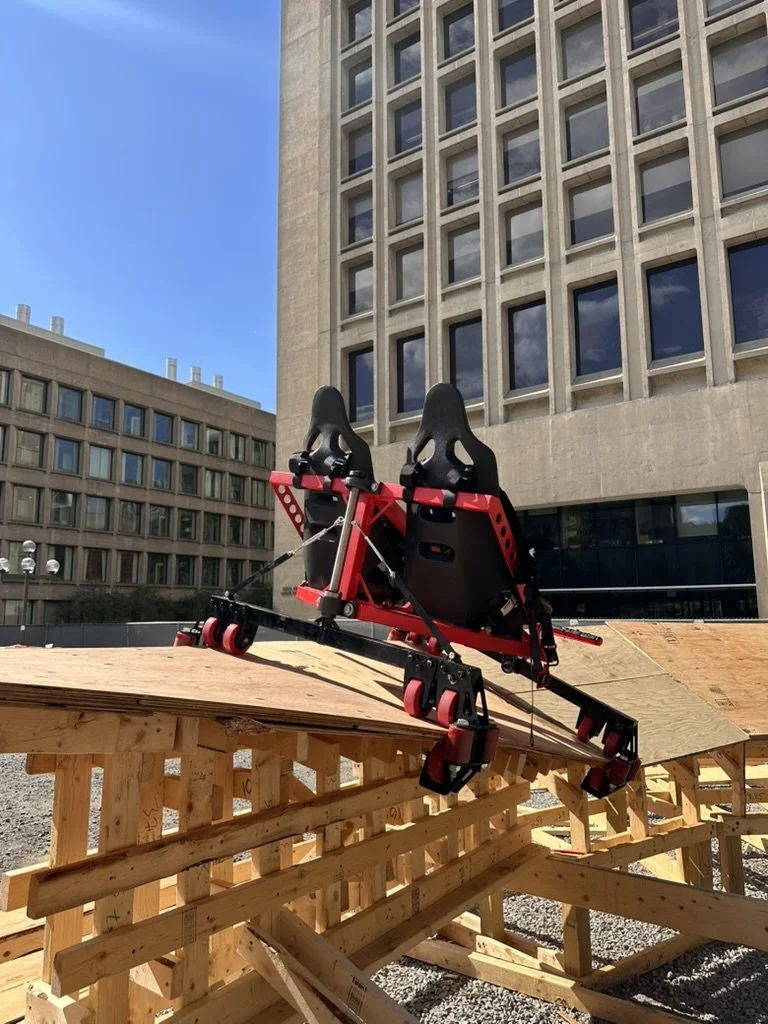
The last thing to analyze was the wheel modules themselves. Each wheel module holds 3 wheels: main wheels, upstop wheels and side wheels.
The inner wheels are not analyzed because, as previously established, the strength of the cart is sufficient without having these wheels share the load.
The stresses on the wheel mount from the main wheel were analyzed using a force of 1740 / 4 = 435 lbf assuming the maximum vertical load from the cart is shared amongst all 4 wheels. The factor of safety was very high (≥ 10).
The upstop wheels were analyzed by applying the same 435 lb load to its mount. As noted previously, loads this high are not encountered in the coaster but the factor of safety was still very good, around 3.
The side wheels were evaluated by applying the shear force divided by 4, assuming it would be shared across the 4 wheels in contact with the side of the track (2 on the front and 2 on the back bogie). So, 2460 / 4 = 615 lbf was applied to the mount for each wheel. The factor of safety was around 2.
This simulation was the most complex because I had to take into account the bolt that was used to install the main wheel, since it also prevents the metal around it from bending apart.
The small stress concentration observed around the bolt were due to simulation inaccuracies and will not occur in reality, particularly due to the main wheel in place preventing any inward plate deformation.
Fabrication:
To help guide the people fabricating the cart based on my design, I made this slide deck for them to follow. I thew it together really quickly so it is not very polished but it gives you a good sense for the considerations that had to be made when turning the cart into a real structure.