AXIAL FLUX MOTOR:
This is the custom motor that powers my new 30lb combat robot KRATOS. The design of the robot demanded an incredibly powerful motor, that was as lightweight and compact as possible. The only way to satisfy these demands was to build a custom motor ideally suited for this application.
The development of this motor started at the end of the school year in May 2023. Over the course of the summer, I spent all the downtime I had at my internship and in the evenings after work developing this, and the design was finally completed a little over 6 months later.
Once the motor was fully ready, I then spent a few more months designing the rest of the robot around it, fabricating all the parts and then took it to competition.
In May 2024, almost exactly a year after its inception I won first prize at the MIT MechE Deflorez Competition for the motor and robot.
To the right you can see the exploded 3D CAD model of the motor.
Quick Facts:
Peak power: 12 kW (250A at 50V, rated for 200A continuous)
Top speed: 9000 RPM
Power density: 5.88 kW/kg (Compare to the Tesla Model 3 rear drive unit: 6.26 kW/kg)
Weight: 4.5lb
Cost: Approximately $1200
12 Slot, 10 Pole YASA design
WHAT Is (AND WHY) AXIAL FLUX?
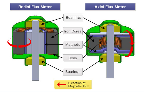
The axial flux motor is a hot technology that is making headlines recently. People are saying it will “revolutionize EVs”, it is unbelievably powerful, etc. In reality, it is not a a new innovation, and pretty simple in theory. Most motors are radial flux motors, where the magnetic field is oriented along the radius (pointing in/out from the center). They consist of a ring of magnets surrounding a ring of coils. In contrast, an axial flux motor has the magnetic field parallel to the axis of rotation. They consist of a disc of coils interacting with a disc of magnets.


There are 5 main advantages to the axial flux arrangement:
Fill factor: the coils in an axial flux motor can be wound using flat rectangular wire, instead of traditional round wire. This leads to a much higher “fill factor”, meaning more of the available volume within the stator can be occupied by copper, meaning more power can be produced within the same volume.
Torque density: generally axial flux motors can use thicker magnets, with each magnet / stator tooth enclosing a larger area. The higher magnetic fields along with the aforementioned fill factor improvements also means that AFMs usually produce more torque for a given size of motor.
Pancake shape: because of the flattened discs of coils/magnets, AFMs lend themselves to a pancake shape which is the ideal fit for the KRATOS robot that has a very short and wide body.
Magnets on both sides: a significant amount of the mass in a motor comes from the “backiron”, which is just a large chunk of solid steel laminate that is needed for the magnetic field to properly travel between coils to maximize the available torque. In an AFM, the backiron of the stator can be replaced by another disc of magnets, which usually weighs less and doesn’t need as much cooling.

Heat Dissipation (the big one): radial flux motors are either built as “inrunners” where the magnets lie in the center of the stator, or “outrunners” where the spinning ring of magnets surrounds the stator. Both of these have disadvantages. With an inrunner motor, you can easily cool the stator from the outside, but they produce much less torque. Outrunners produce more torque but its very difficult to cool the stator since its blocked by the rotor on all sides. Axial flux motors don’t have this problem. Since the spinning magnets are on the top (and bottom), you can make direct contact with the coils from the side and cool them really effectively. This is key. The more heat you can extract from a motor, the more power you can put into it. Motors are generally only thermally limited, the only reason you can’t keep putting more and more watts into your motor is because it will eventually get too hot. (Unless its mechanically really flimsy).
You can see the deliberate thermal design to exploit this property in my motor in the image on the right.
DESIGNING THE STATOR:
The biggest challenge with axial flux motors (and the reason why they are not very common) is building the stator. Eddy current losses dictate that the stator must be made from soft magnetic composite (an expensive, hard to use material) or laminated electrical steel. SMCs were completely out of the scope of this project. They require custom tooling and are very hard to obtain. However, the laminations need to be formed in this sort of crown shape for the stator, with lamination layers in circular rings out from the center. This is an incredibly difficult shape to make from flat sheets of metal that are glued together, and the narrow channels make it very hard to wind copper wire through the stator, especially when fill factor (using all the available open space) is a priority.


To counteract this, I adopted a new design with a couple significant improvements. The coils are pre-wound from flat rectangular wire, maximizing fill factor and saving the effort of having to wind wire in between all the stator teeth. Next, each tooth of the stator is split into two halves, which are much easier to make from flat sheets instead of the circularly winding laminations that are traditionally done. The coils then slide onto each half tooth, and the half teeth are then glued together to form one segment of the stator.
My design is a so called “YASA” (Yokeless and Segmented Armature) motor. In simple terms, it means the stator is made up of a bunch of individual segments (the glued teeth and pre-wound coils), and the motor is symmetric with magnets on both sides of the stator.
The advantages of having magnets on both sides is twofold. It enables the simpler stator construction, but it also saves a significant amount of weight, while keeping the magnetic path optimal.
Optimal Magnetic Design:
In order to utilize the full power of the magnets in a motor, the full path of the magnetic field must be considered. In simple terms, the north and south sides of all the magnets must be connected so that the maximum field strength is concentrated in the air gap where the power of the motor comes from. My entire motor was designed with this in mind. I used high permeability materials to make sure the magnetic field passed through them as easily as possible. The stator is made from electrical steel and the rotor backiron from nickel permalloy (a special material 1000x more magnetically permeable than ordinary steel). The airgap was also precisely tuned with shims after the motor was built to get it as tight as possible.
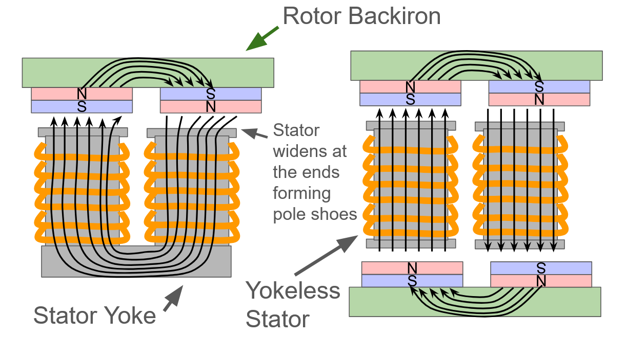
The diagram to the left shows that there are generally two ways of building an axial flux motor. Some motors have only one disc of magnets, and a stator yoke completes the magnetic circuit on the opposite side of the coils. I elected not to use this approach because pre-wound coils cannot be slid on to this type of stator (since the wider pole shoes are required at the top to prevent eddy current heating within the magnets). The YASA construction has magnets on both sides, eliminating the need for a stator yoke, because the bottom disc of magnets with opposing polarity handles the magnetic field on the other end of the stator. This saves the weight of the stator yoke, which is usually a big chunk of steel. My magnet discs are especially light because the nickel permalloy is so permeable I can get away with just using a thin layer. Having a whole second disc of spinning magnets on the bottom side is actually lighter than the stator yoke would be.
I confirmed this decision with simulations in Ansys Maxwell which you can see below. All of the brightly colored lines are magnetic field lines (illustrated with the black arrows in my diagram). The color corresponds to the strength of the magnetic field in that region. The simulation shows that the magnetic field strength of the yokeless design with magnets on top and bottom is the same if not better than the motor with magnets on only one side.


MOTOR COnSTRUCTION:
This lead to the motor having the construction illustrated below. Rings of coils are slid onto rings of stator teeth, with a few PCBs holding everything together and making the connections between the ends of the coils. An aluminum hub in the center holds the bearings that the rotor disks spin on and an aluminum housing supports the coils on the outside with heatsink fins to dissipate heat.
OPTIMAL POWER DENSITY:
The entire reason for building my own motor was to pack the maximum amount of power into the KRATOS combat robot. The motor needed to be able to handle 250A peak currents, and 200A sustained currents at 50V. This amount of power demands thick copper conductors, 8 mm^2 by my calculation. Additionally, maximizing power out of a motor means a high fill factor. Both of these demand a large cross sectional area of copper.
However, doing this also presents issues. When electricity flows through a thick wire at high frequency, it gets pushed to the outer rim of the wire due to the skin effect. Additionally, the torque of a motor is proportional to the number of turns in the coils. To fit more turns in a given area, each individual turn must be made from thinner wire.
Thus there are two competing influences, as shown below:

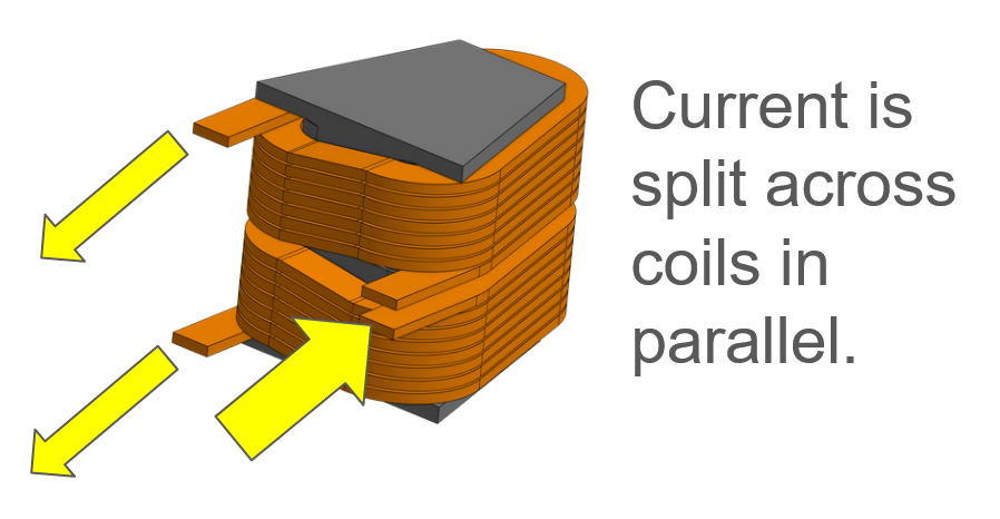
I rectified this with another unconventional motor topology: phase coils in parallel. In my motor, each segment of the stator consists of two coils on two half-teeth. These coils share the total current (only 100A each) so they can be made from 4 x 1mm rectangular wire. The total current still passes through 8mm^2 across both the coils, but since each conductor is thinner, the skin effect is much less of an issue. Additionally, the thinner conductors are easier to bend into the necessary triangle shape. They have a smaller minimum bend radius meaning the triangles have sharper points, a larger enclosed area and can thus capture more flux, leading to more torque. Thinner coils are cheaper too.

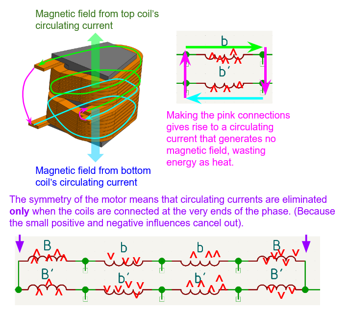
However, connecting the coils in parallel creates another problem. While the motor is running and the magnets are rapidly moving over the coils, small variations in the positions of the magnets, their distances from each of the two coils, the magnetic field escaping from the stator steel, etc. mean that one coil within a stator segment will have a slightly higher voltage than the other. Within one phase of the motor, all of the coils will have slightly positive or negative influences of varying strengths due to these factors.
It’s very tempting to directly connect the two coils in each segment together to simplify the wiring. But, in this arrangement the subtle voltage difference will give rise to a circulating current that would cause excessive heating in the motor and significantly reduce how much power it can handle.
Luckily, since my motor is symmetric with 12 coils and 10 magnets, these influences exactly cancel out when the 4 coils in series are connected at the ends. This led to my final wiring arrangement for the motor, with 24 coils in total, 8 per phase and 2 per stator segment.
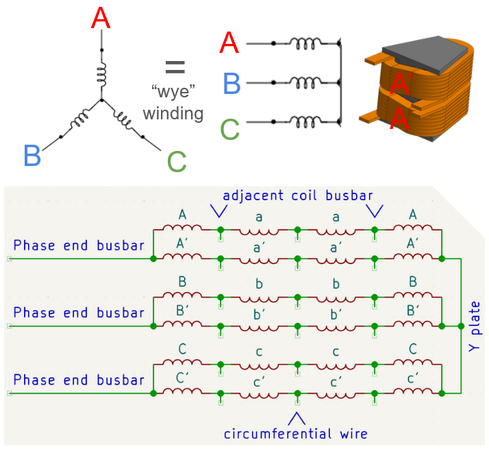
All the connections in this motor need to be able to handle the extremely high current demands, so they are almost all made with solid copper busbars soldered as close as possible to the ending tabs of the coils. When the current has to be passed around the circumference of the motor, I use specialty stranded-core wire with the thinnest insulation I could find. It runs along the heatsink on the outside, so the thin insulation allows heat to escape the wire as fast as possible.
Altogether this gives rise to the winding pattern shown below. The majority of the time spent designing this motor was dedicated to making this wiring scheme as compact and efficient as possible. The heatsinking walls of the motor needed to be as close to the coils as possible to pull heat out of them, so there is very little room to connect all the coils around the outside. I achieved all of the 48 connections for the 24 coils in just a narrow 5mm band around the outside of the motor.


