Battlebots CONTROLLER:
My robotics team could not meet in person in 2020 due to the pandemic, so we could not compete in FIRST Tech Challenge like we normally do. Instead, we tried to run a 3D printed battlebots competition amongst ourselves. The team split up into 3 person groups to design and build their own robots, while remaining fully remote.
Alongside organizing the competition and setting up the rules, I designed the hardware that makes the entire remote event possible. My custom control board was going to be the brains of each team members’ battlebot, and allows them to be controlled over the internet.
This meant that one person could host the competition, livestreaming the arena and setting up all of the robots. Each competitor watches the livestream and pilots from their own home, using the free app Blynk. This allows for a physical competition without people meeting face to face.
We also worked on building an arena for the competition, based on the FIRST Tech challenge field we already had, but enclosed with 1/4 inch thick acrylic to prevent parts from flying out.
We hoped to reuse this hardware to run battlebots competitions at outreach events and in our noncompetitive club at school.
Unfortunately, this was quite an ambitious project, and we did not have time to finish it before the school year ended.
3D Models of CONTROL BOARD AND ARENA:
Capabilities of Control BOARD:
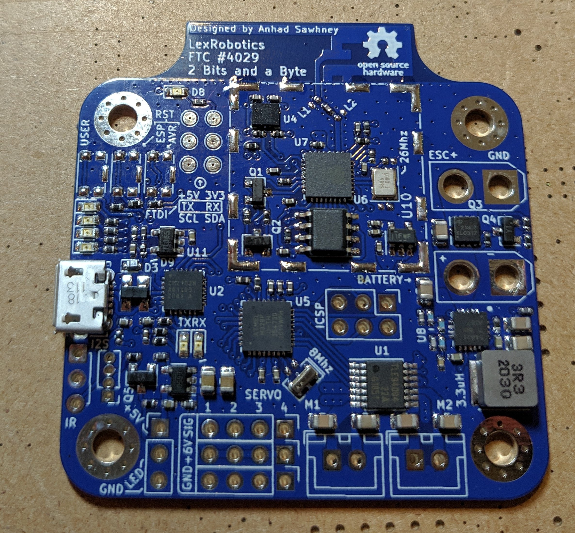
This board is one of my most complex. It is a densely packed 4-layer board, that involves everything from sensitive wifi signals to powerful motor controllers. It also has several safety features to ensure that the combat robots can be shut down in an emergency, even when damaged. Feature list:
ESP8266 WiFi-enabled microcontroller (This is what controls the robot and connects to the internet. It is protected under a metal can to block electrical noise, and its antenna is built into the board.)
Atmega328P microcontroller (The ESP8266 does not have enough pins to control all the motors and servos in a combat robot. It sends commands to the Atmega328P over I2C, which then runs all the peripherals)
USB port to program the ESP8266
LED battery level indicators
IR receiver emergency stop (This functions like a TV remote receiver. As soon as it gets a signal, it commands the Atmega328P to shut down power to everything else on the board, and keeps the robot powered off until the next time power is connected. This is the most critical safety feature, and it works even if the ESP8266 dies.)
These peripherals can be connected to the control board:
WS2812b RGB LED strip
Up to 4 servos
2 DC motors
Brushless DC motor + ESC
The control board had to go through a couple of hardware revisions.
CONTROL BOARD V1 SCHEMATIC (CLICK TO SEE FULL IMAGE) AND DEMO VIDEO:
This is my friend testing the prototype I built, using his phone to control some motors.
2D MODEL OF CONTROL BOARD:
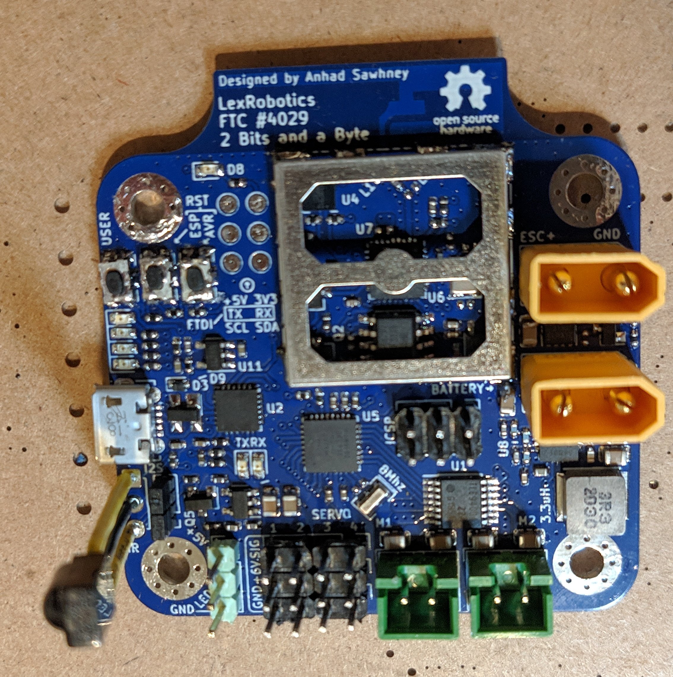
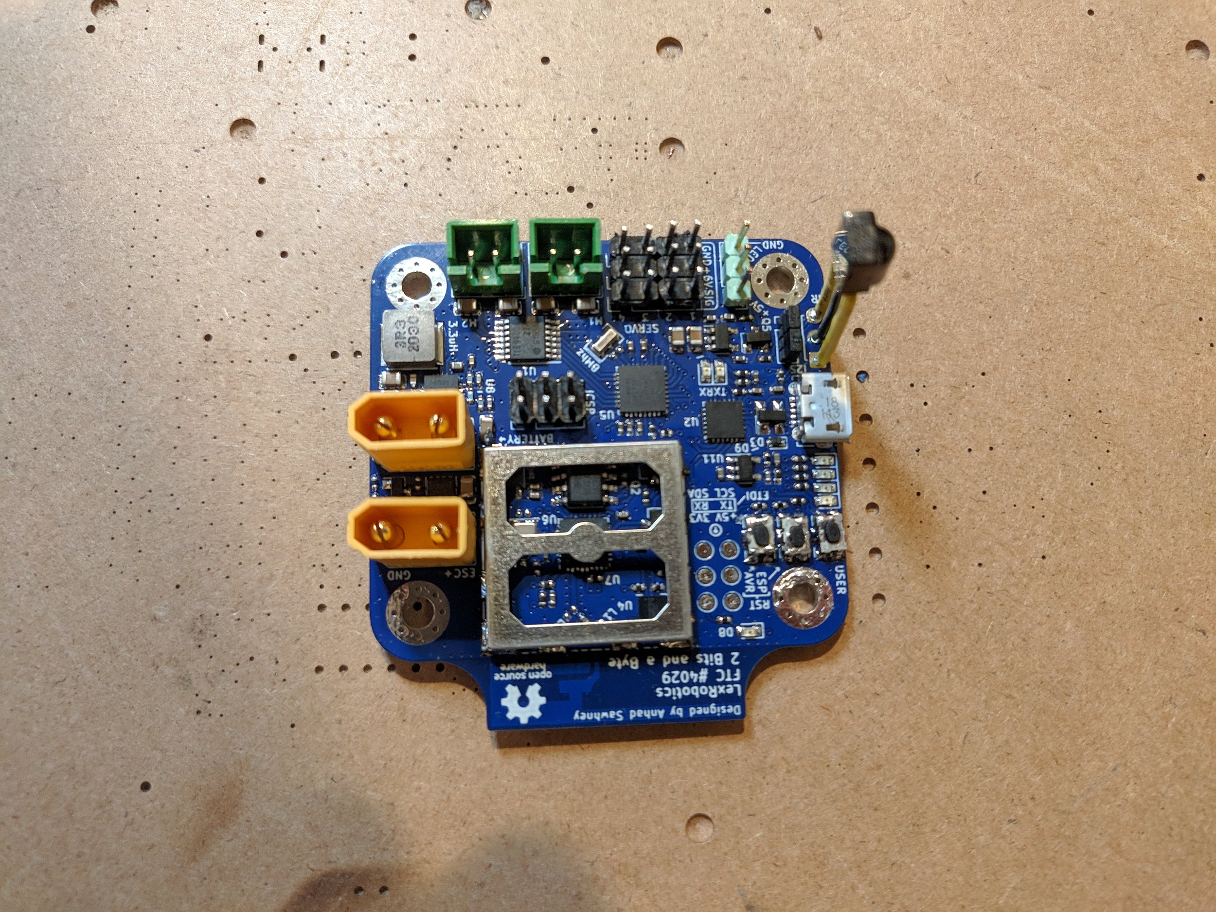
Manufacturing Version 1 of the ContRol board:
The board was manufactured by PCB way, using their assembly service. This meant I did not have to do any of the SMD soldering. Although I could have done it myself, I chose to have a factory do it to save time and effort.
I still had to do the through-hole soldering of all the connectors and the RF shield.
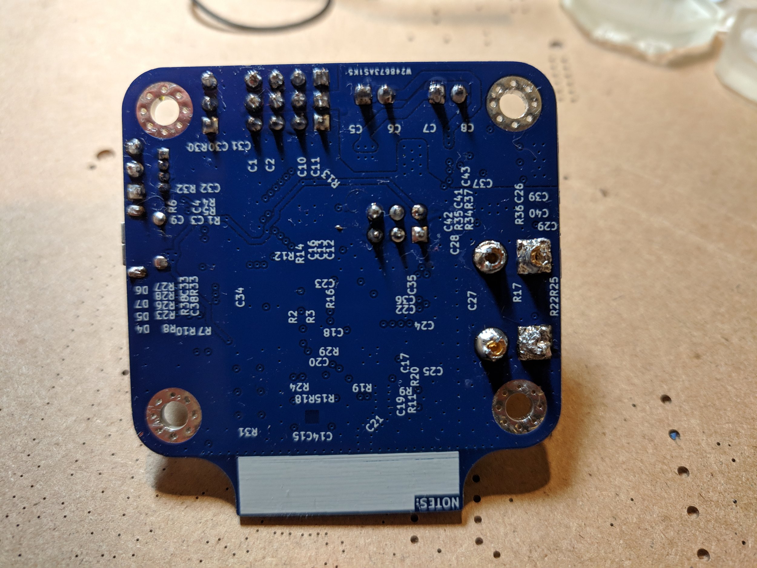
Problems With Control Board V1:
Unfortunately, this board had a lot of problems, mostly because my first design was quite complex. The USB port and the ESP8266 Wifi-enabled microcontroller did not work. In addition, the motor driver was not getting power.
I tried to fix the USB port by cutting some incorrect traces on the PCB.
This did fix the USB port, but soon after I discovered the other issues and realized I would need a whole new hardware revision to fix them all.


Control Board Version 2.
I simplified the design a lot with this revision. Originally, I tried to do all of the ESP8266 microcontroller circuitry myself all under an RF shield. This caused lots of problems because there were a lot of minor details to get right and it was very hard to debug. This time, I replaced that entirely with an off-the-shelf ESP8266 module which has its own antenna, and packages everything together on a separate PCB, exposing only the necessary pins. This simplified the design significatly.
I also fixed the power supply circuitry and used a different chip to handle the USB communication.
Unfortunately, this design still did not work completely. By the time I received the finished boards, the school year was wrapping up, so I did not get a chance to rectify all of the problems.


