EYES OF THE BASILISK
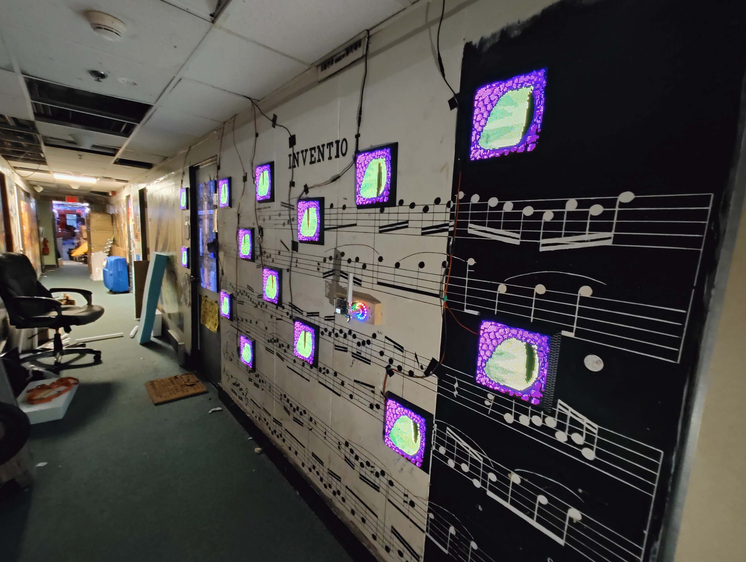
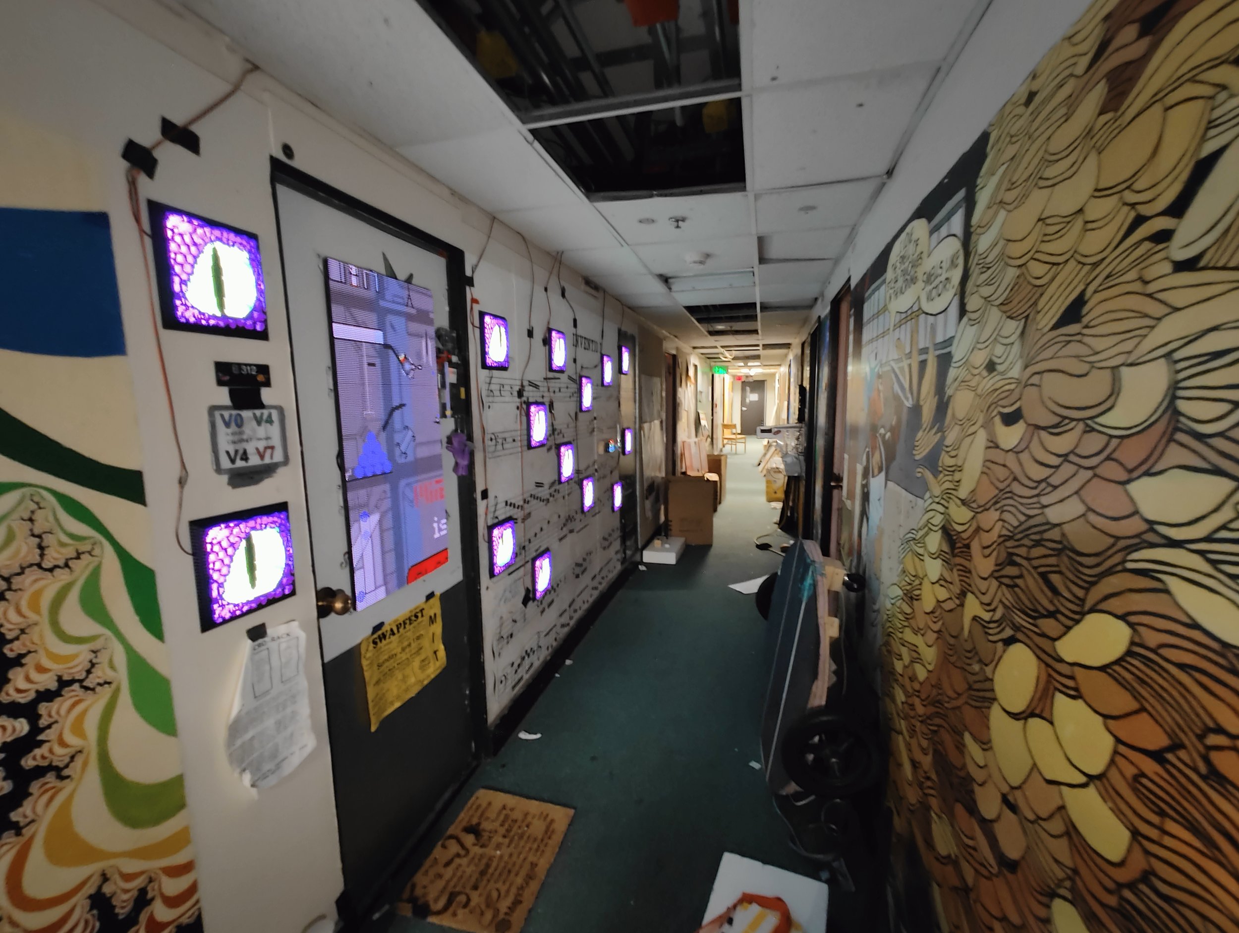
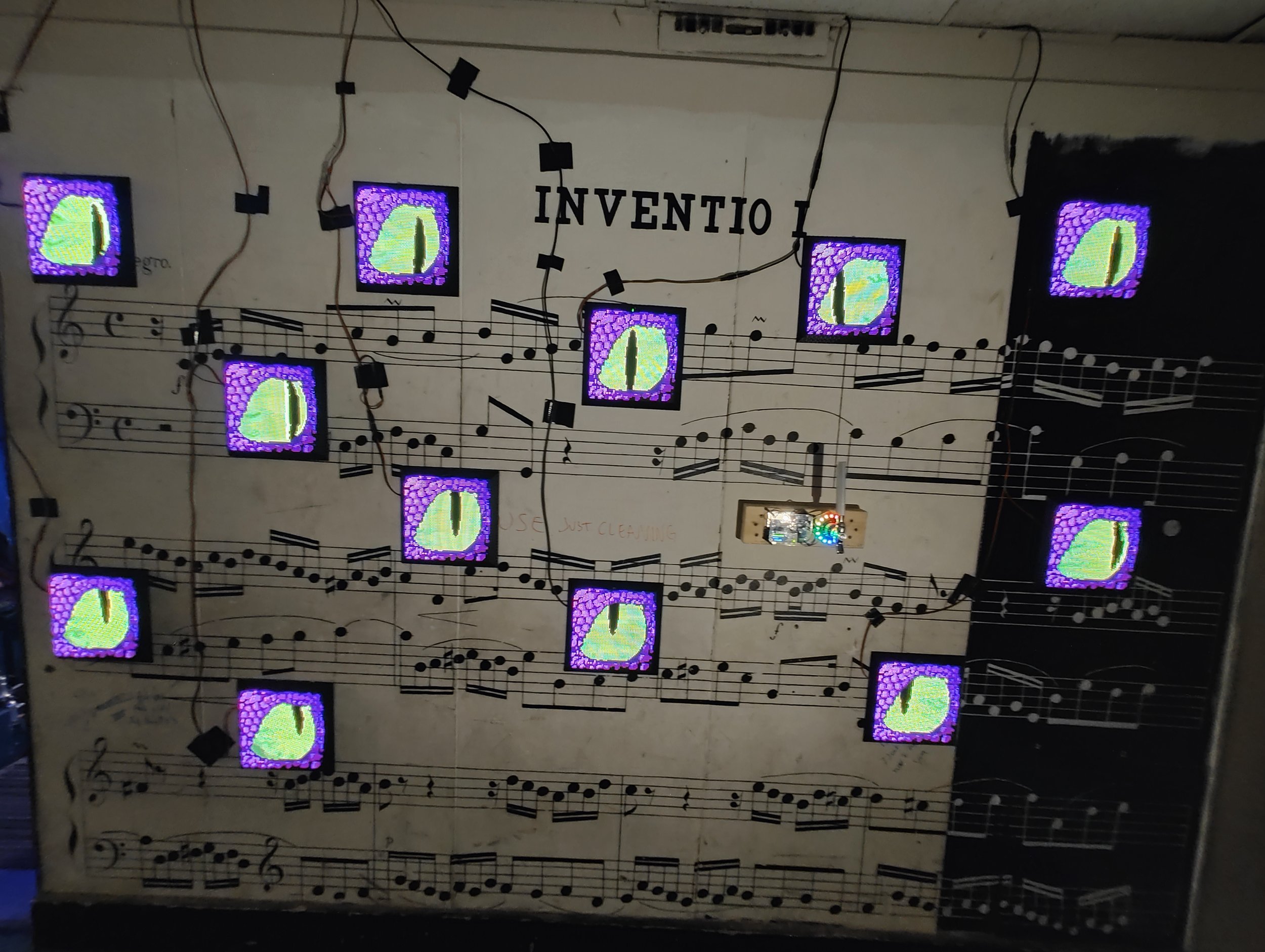
One day while walking home from class I wondered what it would be like to have a room filled with eyes that follow you as you move around. I thought it might be fun so I decided to build this along the wall in the hallway next to my room. I call it the “Basilisk” after the mythical creature that can kill you if you make eye contact with it.
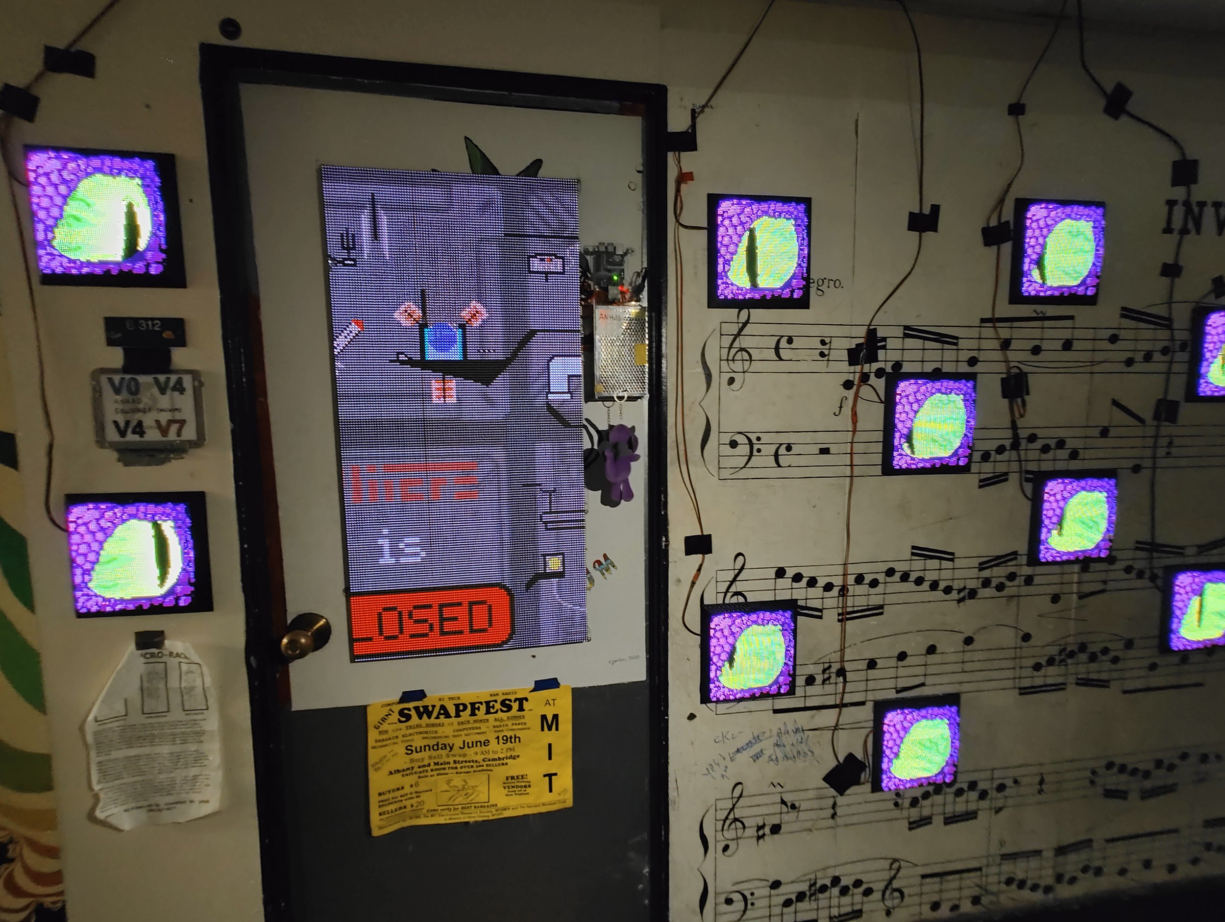
The project consists of fourteen independent but identical panels. Each panel has a 64x64 RGB LED matrix and a custom PCB with a few sensors, ESP32 microcontroller, and some other power delivery and control electronics. A 32x24 thermal camera on the PCB captures the view of the hallway from each eye’s perspective. Ten times a second, each panel takes a picture, scans the picture for a large blob of warm pixels (indicating a human) and generates an image of a monster eye looking in that direction.
Here’s a video of the whole installation in action:
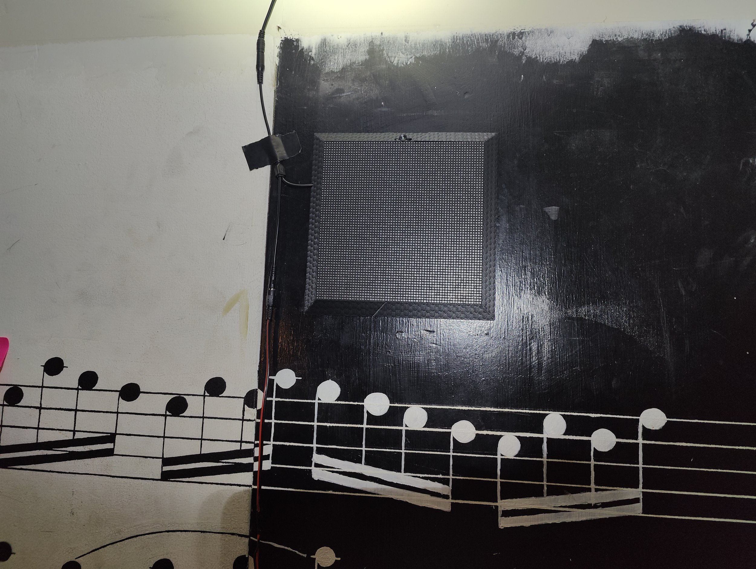
I started the project by making a proof of concept of the electronics on a breadboard. This prototype simply consisted of the thermal camera and LED matrix, to see if I could get a suitable image from the camera and update the image fast enough using the limited computing power of the microcontroller.
The image on the left shows the prototype, programmed to simply display the thermal image from the camera on the LEDs. Hot pixels are colored blue, and you can see me holding my hand over the camera.
Once I knew that the hardware was up to the task, I got to work designing a PCB. Since I have designed many PCBs before, I took this opportunity to teach PCB design to some of my friends who were eager to learn. They did the preliminary design work, and I cleaned it up afterwards.
Here is the schematic and resulting board design:


The schematic is fairly simple. A couple things to note is that there is a USB port and FTDI chip allowing the ESP32 to be programmed and powered over USB. However, since the power from the USB port is not enough to supply all the LEDs, there is a barrel jack and buck converter which takes 12V from a wall power supply and steps it down to 5V, supplying up to 5A for the LEDs. Then there are two level-shifting ICs because the ESP32 microcontroller runs on 3.3V but the LED drivers are controlled with 5V logic. Finally, there is the thermal camera, a light-dependent resistor (because I originally wanted the eyes to only show up in the dark) and a status LED.
The board design for this project was a little bit unconventional since it had to fit squarely within the commercially-available LED matrix. I wanted to simply plug into the back and make all the power+data connections, as well as position the thermal camera in the right place, so I had to take careful measurements of the locations of all the connectors and mounting holes to make sure everything lined up. This allows for a very clean build with minimal wiring required once the boards have been assembled. The drawback of this approach is that it’s very tightly integrated to the specific LED matrices I bought since other matrices will have the connectors and holes in different places, and many manufacturers don’t really provide information on where they are.
Here is a 3D model of the resulting PCB.
After finishing the PCB design and ordering them, I got to work on the frame around the panel. I knew I wanted a cleaner look than just bare electronics mounted to the wall, so I designed a 3D printed frame that screws together onto the matrix. It holds and protects the electronics, and also have locations to attach 3M Command Strips so that the panels can be easily stuck onto a wall, and removed if necessary without damaging the paint.
Here’s a 3D model showing the board attached to an LED matrix panel, and the frame I designed around it:
The final step before the parts arrived was to write the software. For this my friends and I wrote a python simulator to get the graphics working first before we ported it to the microcontroller. I was pretty unsure of how to animate the eyeball looking in different directions in a convincing way, so I wanted to quickly try many different approaches in python because its much easier to debug and test without having to flash the ESP32 every time.
I started with a bunch of pixelart frames of the eyelid at various stages of blinking and the eyeball looking in different directions.
I first had the script simply display a skin picture and then pick the eyeball picture closest to where the mouse was on the image. Clicking would cycle through all the skin pictures, giving a blinking animation. I had originally intended to morph between the different iris positions in some way, but I could not find a good way to make this work without it seeming “flat”.
Ultimately I did get a spherical looking eyeball, just using the image where the iris is in the center. I wrote my own algorithm to stretch and distort the picture to make it curve like it was a textured sphere. Basically, it shifts each row of the image along a parabola, and the parabola gets flatter when the mouse is close to the center (horizontally) and steeper when the mouse is close to the edge.
Once the parts arrived, I got to work assembling the boards. Because I had to make 14 of the same exact board, I took advantage of a pick-and-place machine that I have access to at the Media Lab. This allowed me to easily automate the repetitive (and error prone) manual placement of delicate SMD components. In half a day a friend and I churned out all 14 boards plus a couple spare. I also used the Media Lab’s 12 3D printers to quickly print all the frames.


After the boards were done, I ported the code to C for the ESP32 and flashed all of them. Then we assembled the boards, LED matrices and frames.


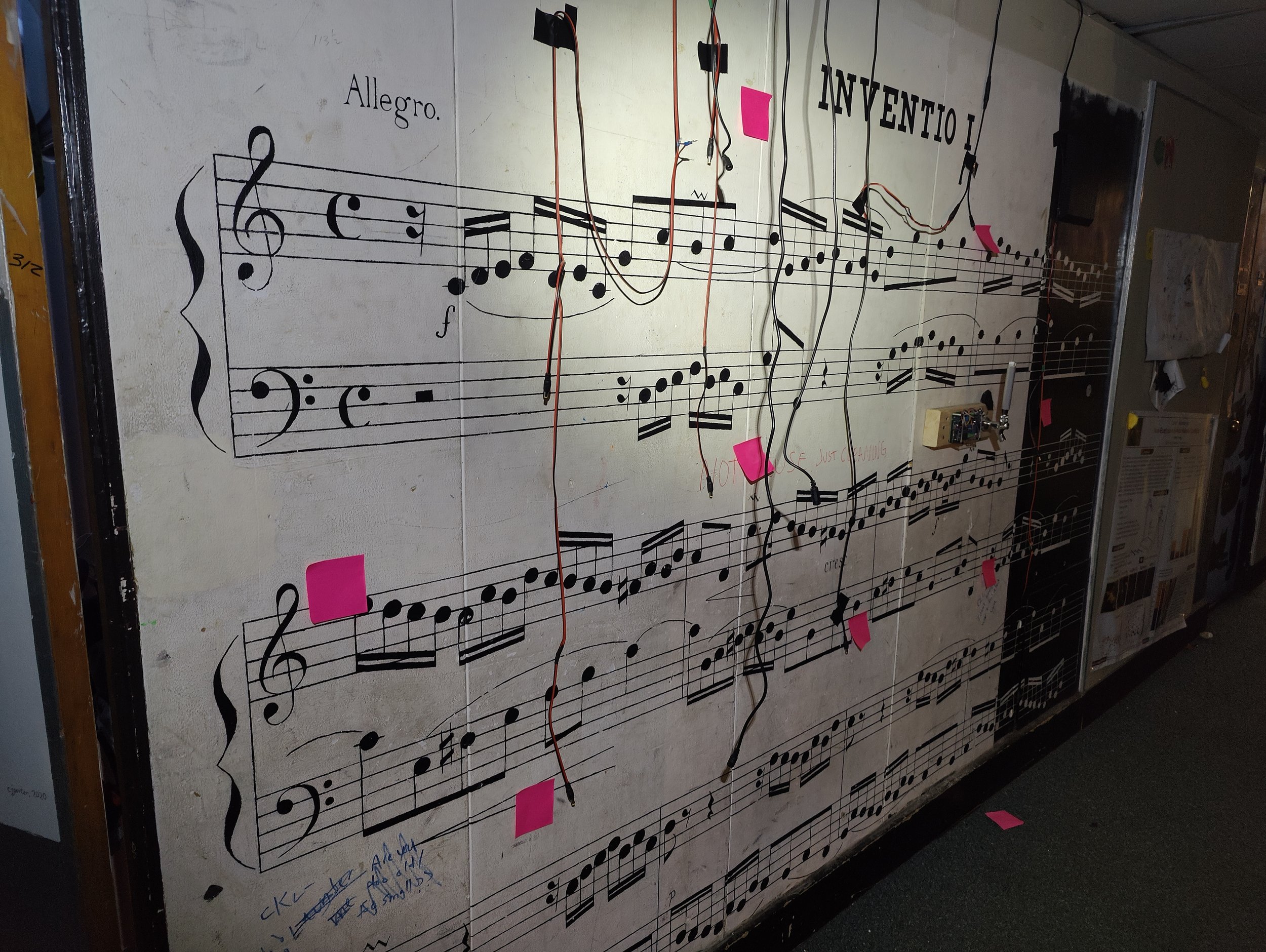
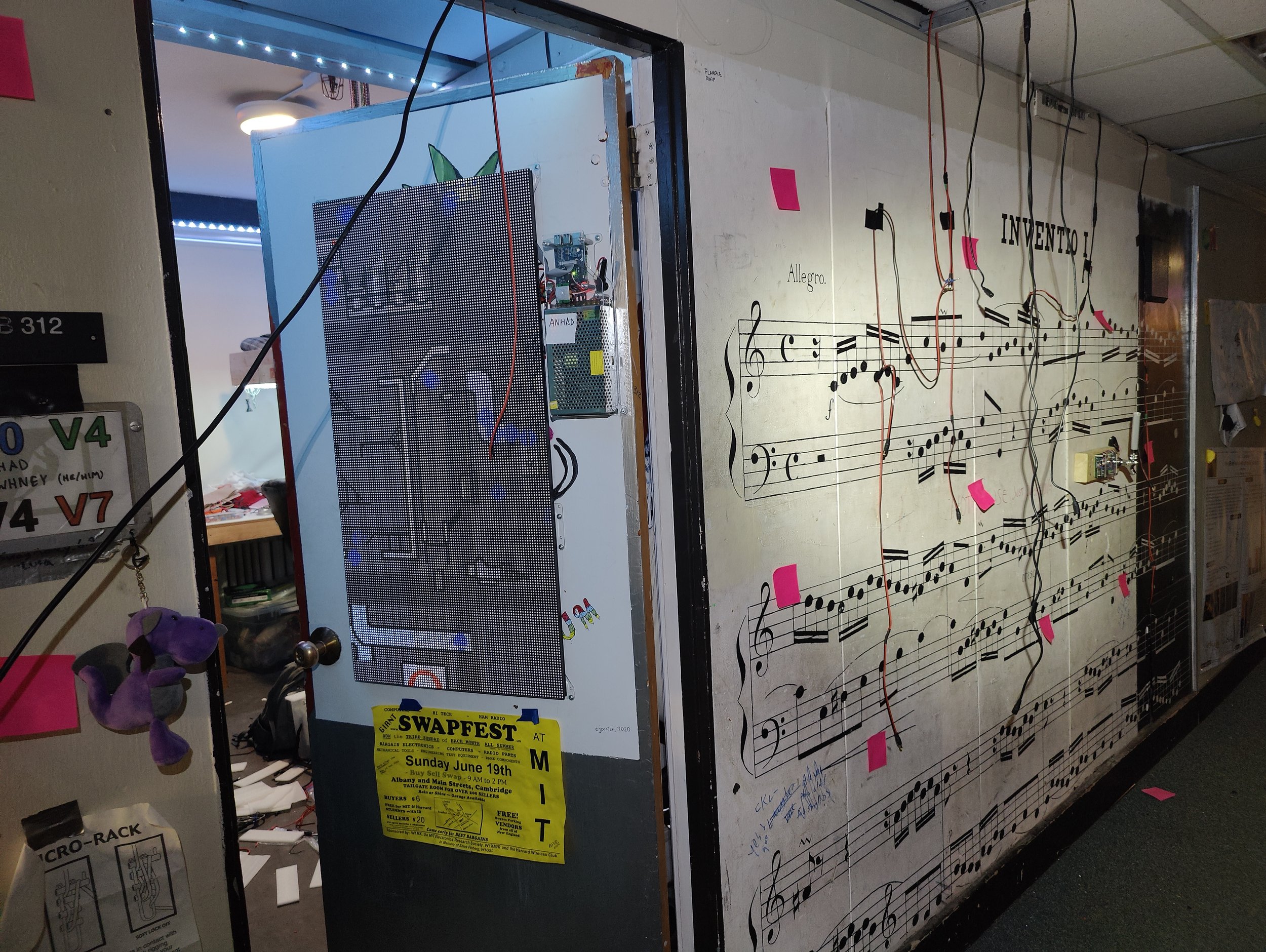
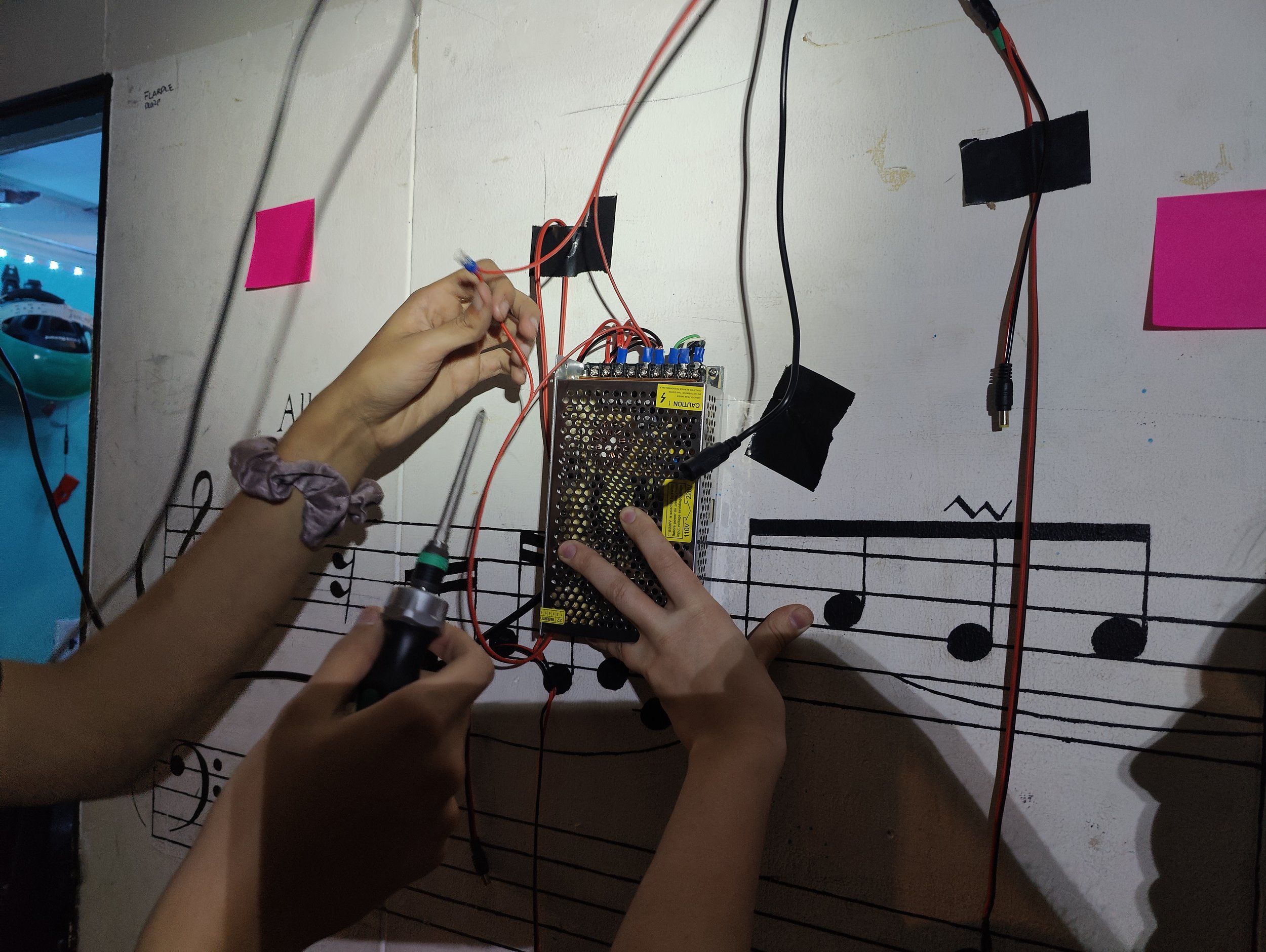
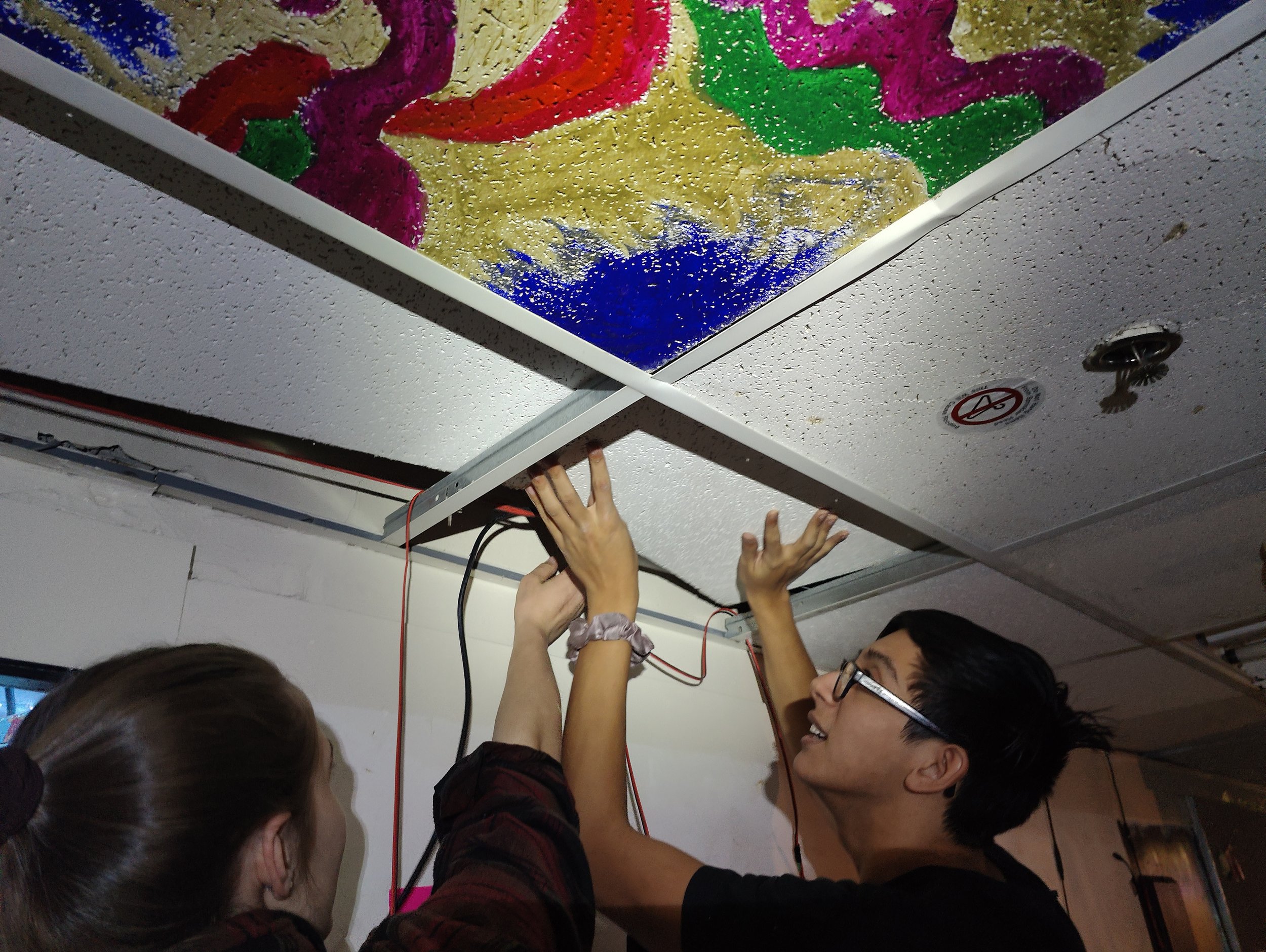
The last step of the process was actually installing everything in the hallway. We planned out the arrangement of the panels with post-it notes, then wired up a 5V power supply to an outlet in my room by drilling a hole in the wall. The power supply was hidden above a drop ceiling tile, and we measured and cut wires to run power to each of the post it notes. Then we stuck the panels on the wall with command strips and plugged everything in.