FPGA COnway’s GAme of life:
Animation of Conway’s Game of Life
This was a final project for my Advanced Computer Programming Class.
Conway’s game of life is a famous cellular automaton that simulates microorganisms following a simple set of rules based on population density. https://en.wikipedia.org/wiki/Conway%27s_Game_of_Life
The simulation is Turing complete and can produce a variety of interesting patterns and emergent behaviors. Unfortunately, the simulation is also very computationally intensive for a traditional computer, which executes instructions one at a time. This is because the state of each cell must be computed individually using the rules, which makes it difficult to observe these patterns on a large scale at a reasonable speed.
An FPGA is the ideal solution for this task. FPGAs are special integrated circuits which can be “programmed” to contain any combination of logic gates and other circuitry. There is no central processor running the program, instead the circuit architecture is implemented directly (although not permanently).
This solution provides an enormous speed increase because it would involve dedicated circuitry for each cell, meaning its state could be evaluated in nanoseconds and all of the cells would also be computed simultaneously.
Getting Started
This project was difficult because it required learning a completely new language that was very different from any other programming language. Most programming languages are designed to run on a CPU and be executed one instruction at a time, however VHDL (the language I used to program my FPGA) was designed to implement the circuitry on the FPGA itself, so everything was executed at basically the same time, which could lead to conflicts.
I started this project with some basic logic gates on the FPGA such as AND, OR and a simple binary counter and adder.
VGA video OUTput
The board I used for this project is a Terasic DE0-CV, which includes an Altera Cyclone 5 FPGA, and various connectivity options. I programmed everything using the Quartus II IDE. I got the onboard VGA port working with a simple test pattern. I also used the onboard clock to animate the pattern slightly.
Variable Frequency Clock
The FPGA can execute Conway’s game of life far faster than the monitor can refresh, and far faster than a human can comprehend. Thus, I set the maximum update rate to 60hz, the same refresh rate of the monitor. I also added a variable frequency clock using the onboard switches to allow the user to select the speed at which the simulation updates.
Final Product
The final product simulates Conway’s Game of life on a 16x16 grid. It outputs everything using the VGA interface and uses the onboard switches and buttons for user control.
The user can directly edit the matrix of cells using the cursor which is moved using the four buttons and changes the state of the selected cell using the switches. The cursor coordinates are shown on the 7 segment displays above the switches.
I also pre programmed three patterns which can run indefinitely to show off the variable frequency control.
The software project involves multiple VHDL drivers to orchestrate the timing of the display output, update the matrix, handle the 7 segment displays and more. From the quartus IDE I also exported schematics from the VHDL code illustrating the circuitry that is actually implemented on the FPGA.


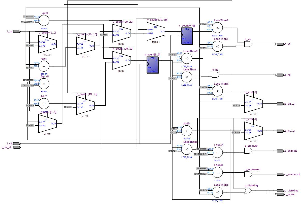

Click on each image for a larger view.