FPV StereoscopiC Video Upgrade:
In building my 3” stereoscopic FPV drone, I decided to revamp the entire stereoscopic video system to make it more robust.
There are two components to this, the dual OSD board and the dual video receiver. I also made a 7W headlight for my 3” drone.
Dual OSD Board:
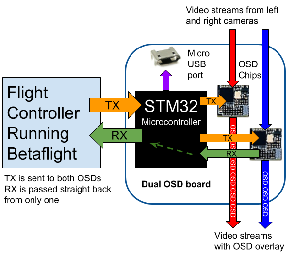
This board is responsible for overlaying the On Screen Display (OSD) information onto the two independent video signals.
The betaflight software that my drones run only have support for one camera system and one OSD to be overlayed onto the camera. My drone is a special case with two cameras, so it holds two OSD chips and mirrors the commands it receives from betaflight to both of them. However, the responses from only one of the OSD chips is relayed back to betaflight.
Thus, betaflight thinks only one OSD is connected, when in fact two are receiving identical commands and overlaying onto separate video streams.
This board went through 3 revisions.
Version 1:
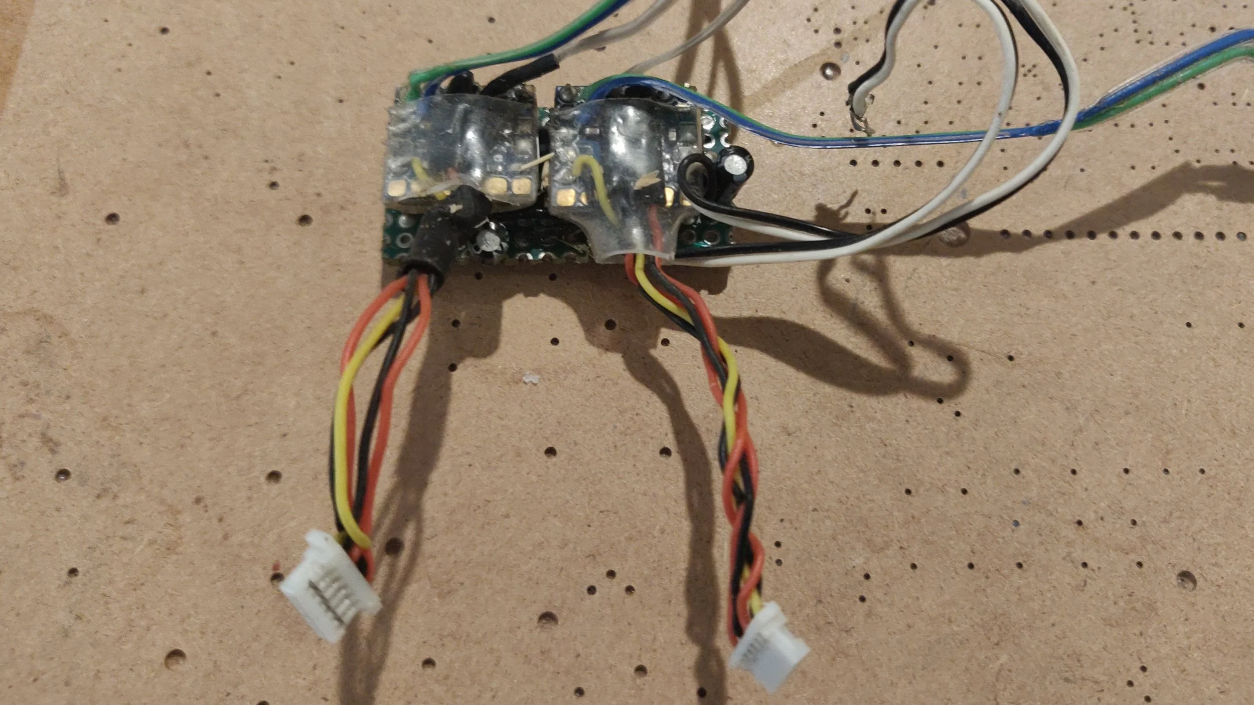
This version had the TX line hardwired to both OSDs and the RX line hardwired to only 1. I made it out of a piece of perfboard and it was meant to be a temporary solution until I could design and build a proper PCB. It had lots of wires sticking out and was pretty janky, but I used it until my 5” drone crashed.
Version 2:
I upgraded this version to do the signal routing to the OSDs using a microcontroller. This meant I could “sniff” the data that was being sent and read it out on a computer to make sure everything was working.
This version included special power filtering circuitry that fed the cameras and video transmitters. The power from the battery was passed through an LC filter with a high inductance and capacitance, in an attempt to reduce noise and glitching in the video feed. The video itself was also passed through tiny filtering chips.
Here are some pictures of the build process. The procedure was identical to any other custom PCB I’ve made.