Green Building Tetris:
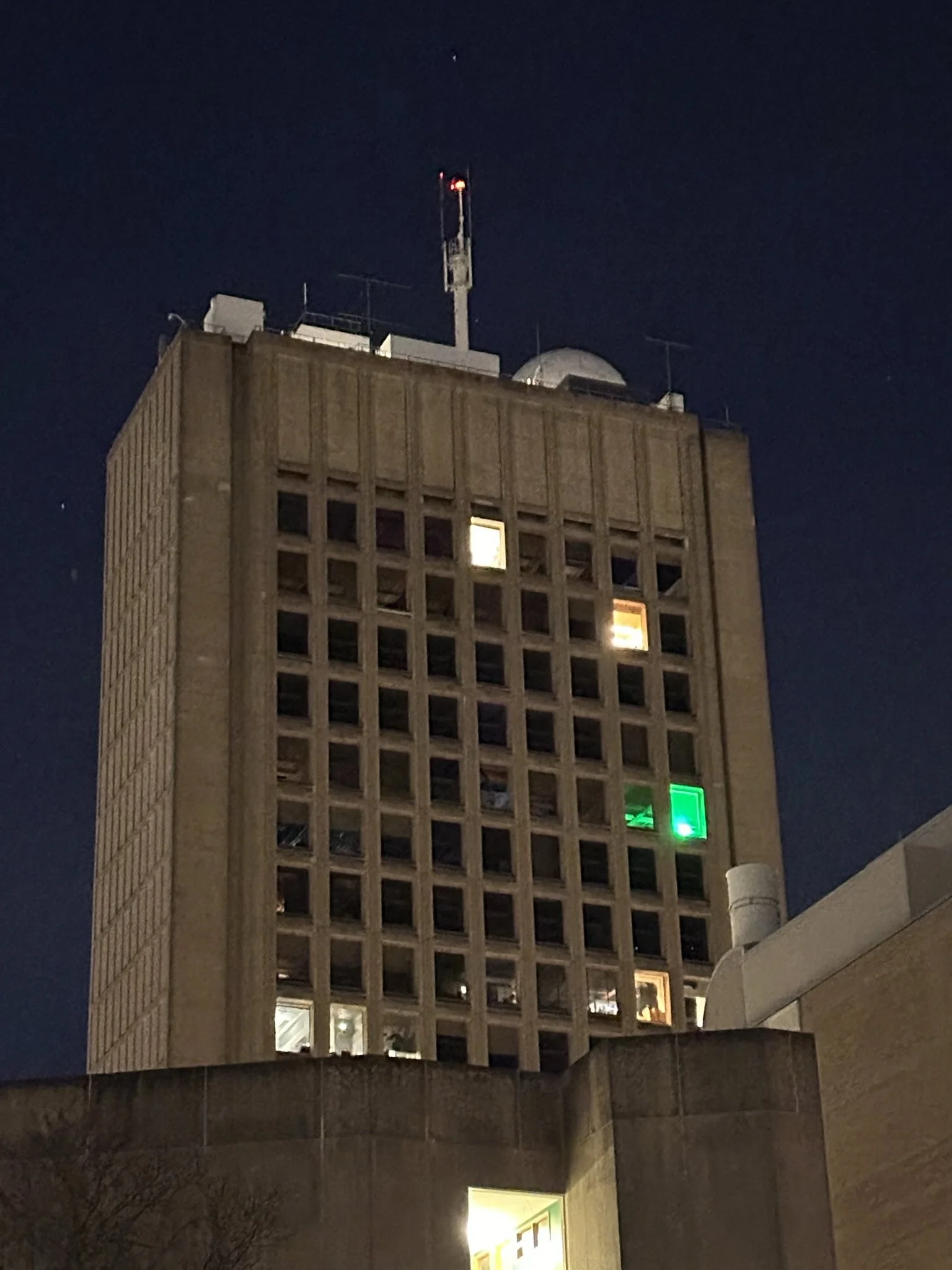
The tallest building on MIT’s campus is called the “Green Building”. It hosts the Earth Atmospheric and Planetary Sciences (EAPS) department, and the front of the building has a very consistent grid of windows. Its prominent positioning close to the banks of the Charles river means that the front of the building can be seen throughout Boston.
It has been a longstanding goal of the hacking community at MIT to use the green building as a giant display to broadcast messages and games. In particular, playing Tetris on the grid of windows was often regarded as the “holy grail of hacks”. Over the course of my final semester at MIT I lead a group of students in building and deploying hardware to convert the entire building into a video display and enabling people to play Tetris or display animations on it. Here are some videos of the end result:
The installation consists of radio-controlled lighting modules installed in each window and plugged into a spare outlet in each room. The hardware is permanent, and the goal of the project was for the Green Building display to remain functional for at least 10 years. Each window unit consumes about 65W of electricity at full power and shines a thin curtain of light that nicely illuminates the entire window outline. Since this building is all offices, it is usually completely deserted after night, so we can shine bright lights in the rooms without disturbing people. A radio base station controlled by a laptop on the ground sends messages to each of the lights to instruct them which colors to display each frame. People can then play Tetris on that laptop, or we can display animations from it.
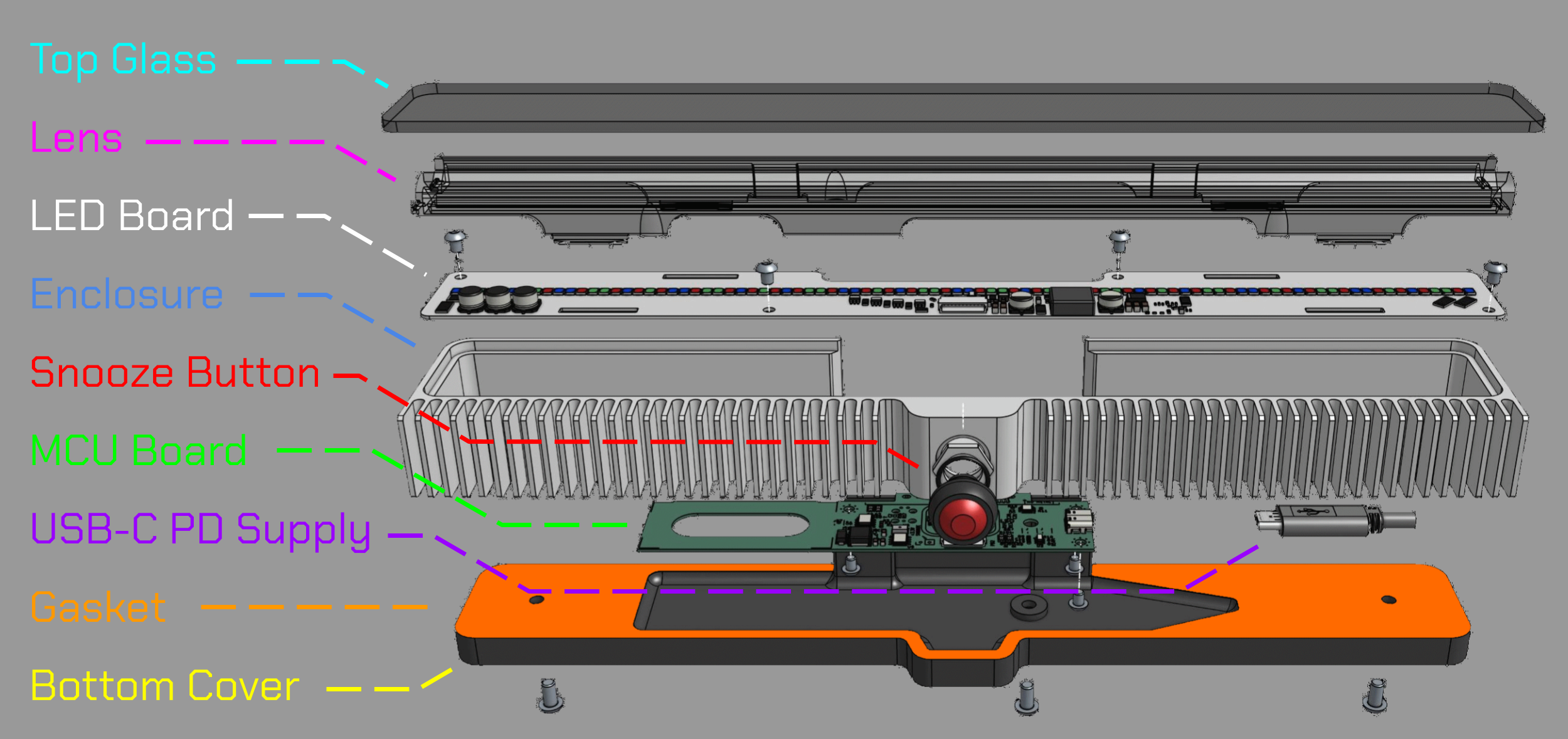
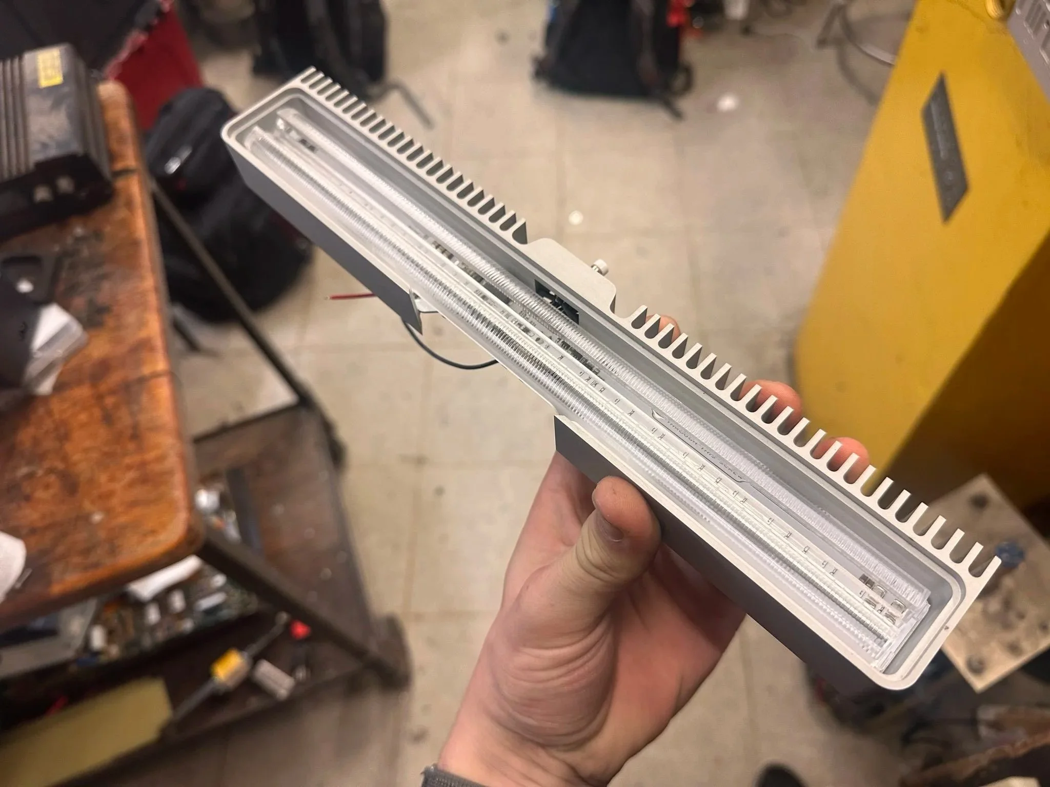
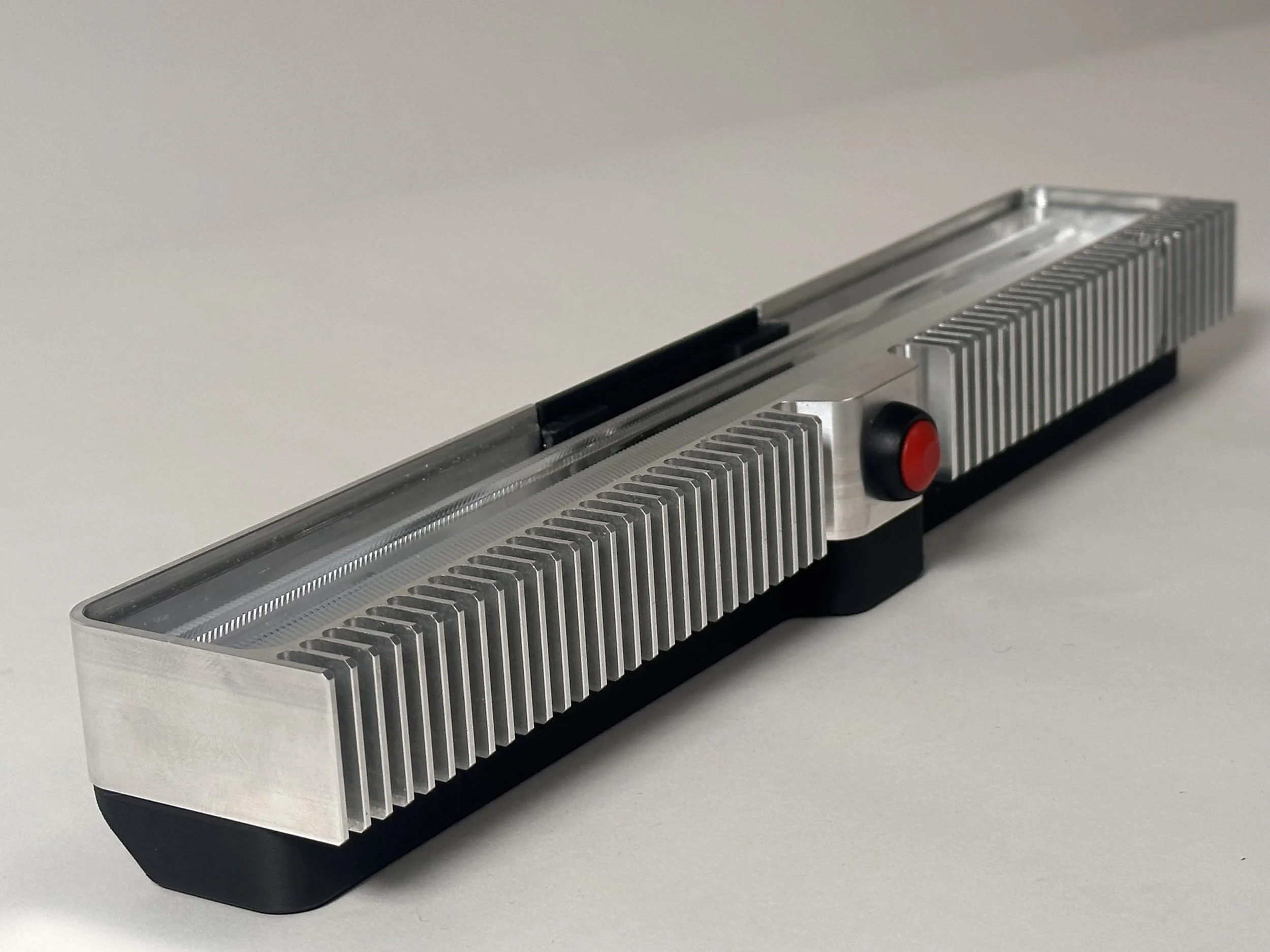
Each window module consists of the following main parts:
A glass plate on the top gets glued in to seal the enclosure from above.
A linear lens mixes and shapes the light from the LEDs.
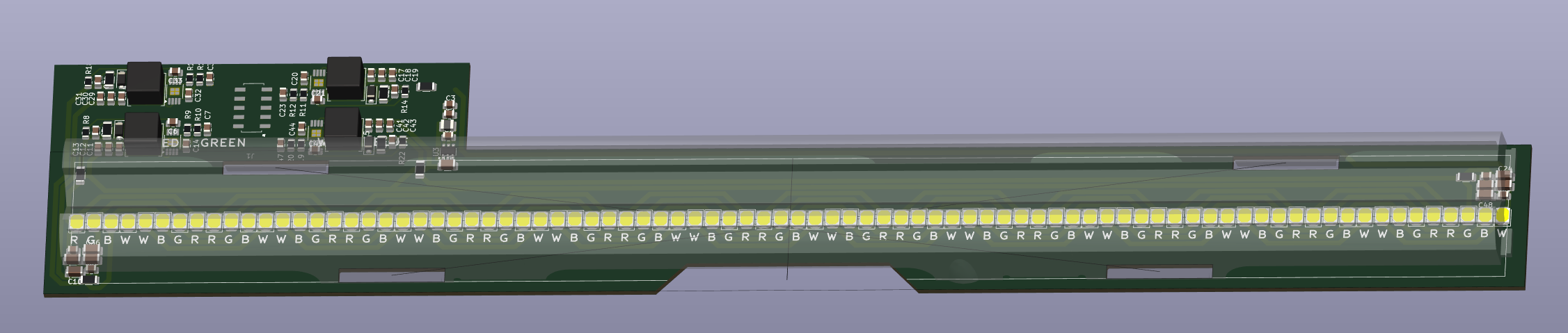
The LED board holds a thin strip of red, green and blue LEDs arranged in a repeating pattern to mix their colors together. It also holds a boost converter and constant current driver chips to power the LEDs.
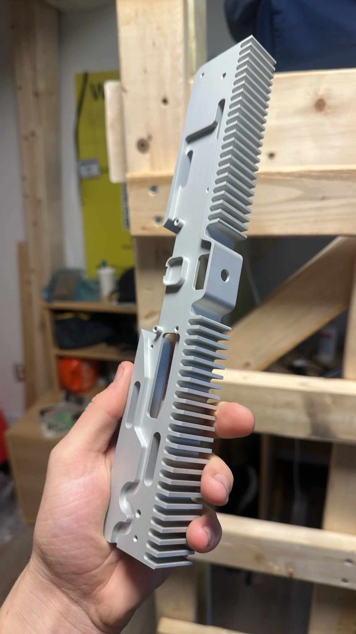
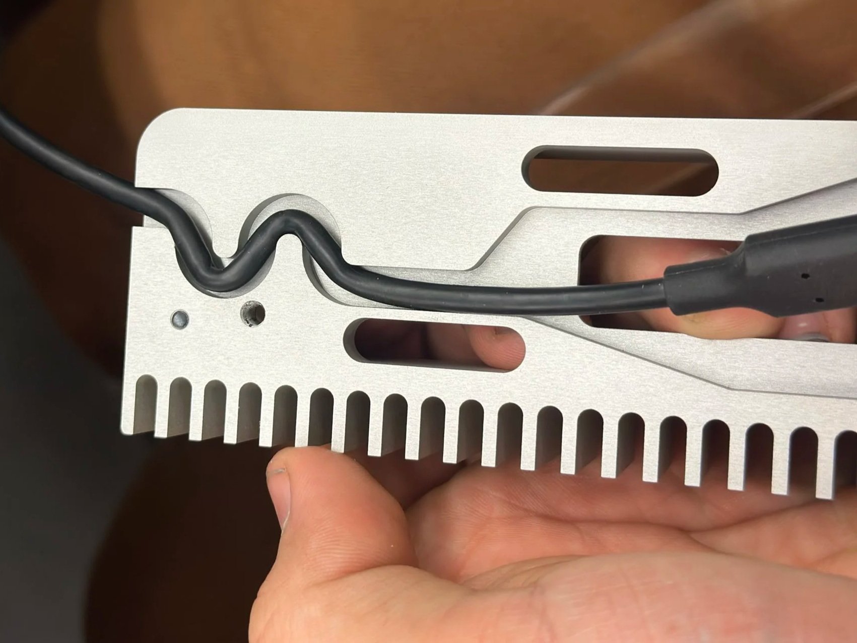
A custom CNC machined aluminum enclosure holds and protects all the electronics, and acts as a heatsink to dissipate waste heat from the LEDs.
The “snooze button” allows people to disable light output for an hour if they are working late in their office while the display is running. An O-ring around the button preserves waterproofing.
The MCU board contains our STM32WL33 microcontroller that is the brains of each unit, and has a built-in radio. An antenna is soldered onto this board, as well as some power management chips and an NFC tag IC which we use to configure the modules before installation.
A 65W USB-C PD power supply powers each window unit. We are also able to use the USB port on the MCU board to program the microcontroller.
A 3d printed piece with a rubber gasket seals the bottom of the enclosure and the region in front of the antenna, while still allowing radio signals to pass through.
I was in charge of the project, and responsible for the PCB design and associated RF + electrical engineering. I lead a core group of about 8 students and guided them in doing the mechanical design, sourcing, software development and mass production to make the project happen. For me, this was the first project I had taken on that involved any kind of mass production. For many others, this was their first major engineering project.
We were not the first group to pursue something like this. In the 90’s, a group of hackers went around turning the room lights on and off to spell “Go Sox” as a static one-night display. In 2012, another group of alumni spent 2 years designing and building radio controlled LED modules to be installed in each of the windows, and they were the first to get Tetris playable on the green building. Unfortunately, their hardware didn’t last very long, and by 2018 the installation stopped functioning. So, in November 2025 I recruited a new group of students to revive the installation by building and deploying all new units that we designed from scratch.
We started this project in November 2025, with the goal to have it up and running by Campus Preview Weekend (CPW, when all the recently admitted students visit MIT) in mid April 2026. We were just barely able to meet this deadline. It took about 3.5 months from initial concept to deployed hardware, and we fundraised and spent almost $30,000 to bring the idea to life. Our efforts were published in the Tech (the MIT student newspaper) and on the admissions blogs, feel free to check out those articles here:
https://thetech.com/2026/04/30/green-building-tetris-2026
https://mitadmissions.org/blogs/entry/the-holy-grail-of-hacks-returns/
Development process
Initial conceptualization (November 2025):
One of the unique aspects of this project is that there was already an existing solution to our exact problem. We were trying to accomplish exactly the same thing as the 2012 attempt, except with improvements to performance, reliability, longevity, ease of maintenance and trying to inconvenience the occupants of the building less.
So, we began the project by analyzing all the issues with the old hardware. We believe the primary failure point was the fact that the old modules left the front open. Water probably condensed on the inside of the cold windows, and dripped down into the modules. (Grad students watering their plants on the windows and spilling some onto the Tetris modules also probably contributed.) We found several with water damaged circuit boards. In speaking with the alumni responsible for the 2012 iteration, they mentioned that this was a deliberate design choice to avoid blocking any of the radio signal and to try and thermally couple the modules to the windows to assist with dissipating heat from the LEDs.
This set one of our primary design goals – that the modules should be completely enclosed and waterproofed. It also told us that heat dissipation and radio reception would be key areas of concern.
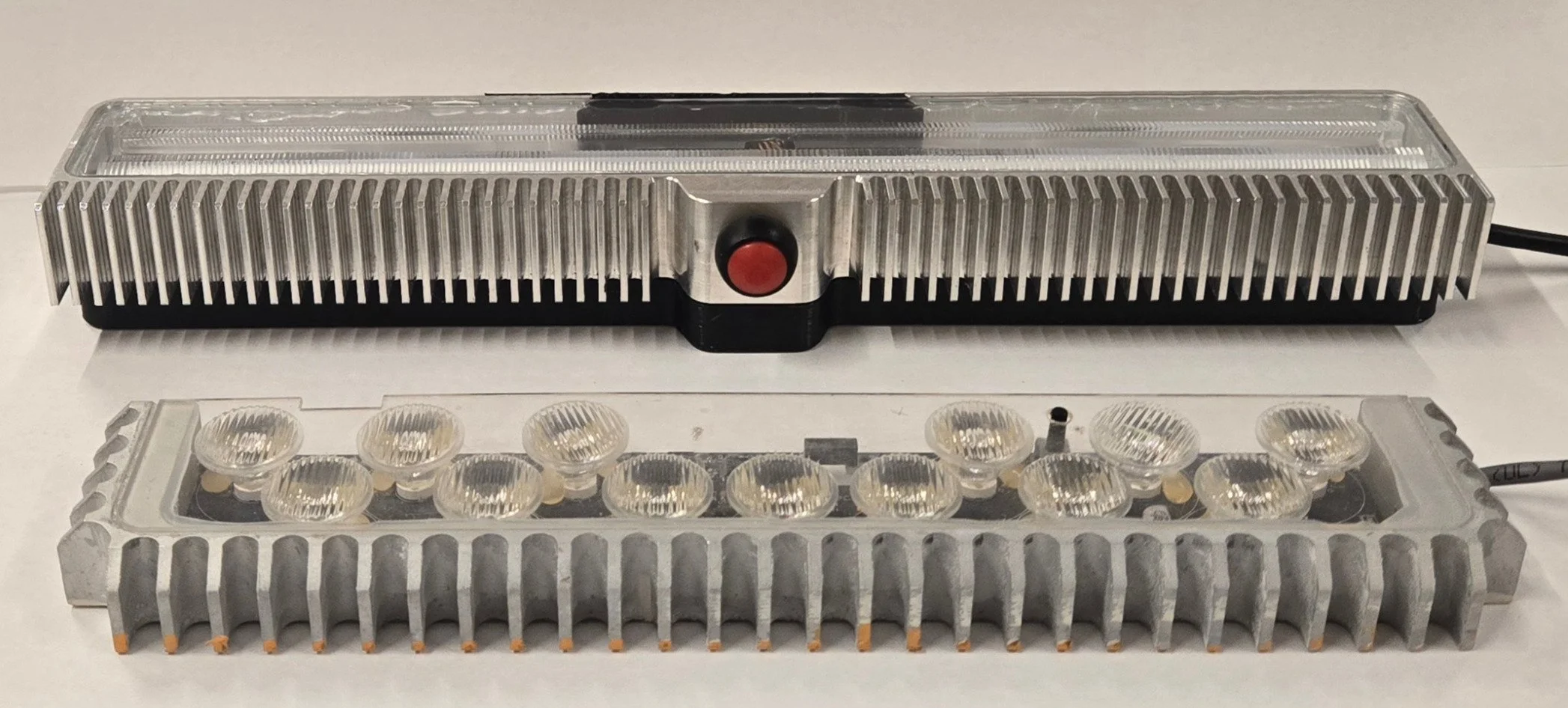
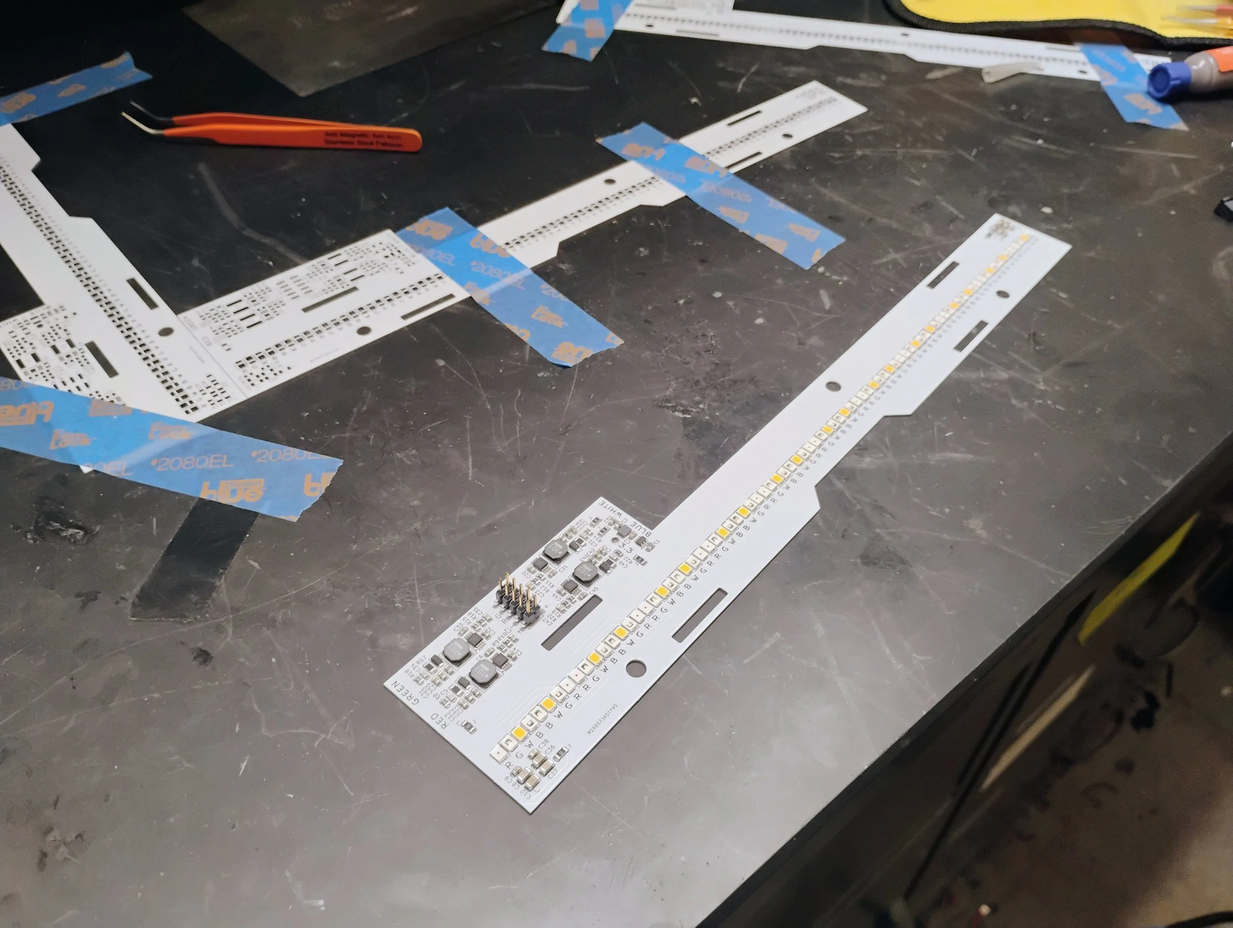
With that in mind, we set about narrowing down the overall size and shape of our modules, which was dictated by our LED solution. The 2012 module used discrete LEDs each under their own lens, and the colors would mix as the projection regions for each LED overlapped on the window. While this worked well most of the time, they had to include white LEDs on their modules since the colors didn’t mix well enough to produce a pure white. We wanted to use a new monolithic linear lens (which probably was not easily available in 2012) that was optimized for wall grazing (illuminating walls with a sheet of light from a module placed very close to the wall surface, almost exactly our application). So I made a test PCB with red, blue, green and white LEDs so we could see what power level was needed to illuminate the window nicely, and whether the colors would mix well enough or white was still necessary.
We placed this PCB in the window and did a variety of tests involving all combinations of colors, curtains up / down, front of the module opaque / transparent, room lights on / off, elevating the LEDs above the caulk border of the window or keeping them as low as possible etc.
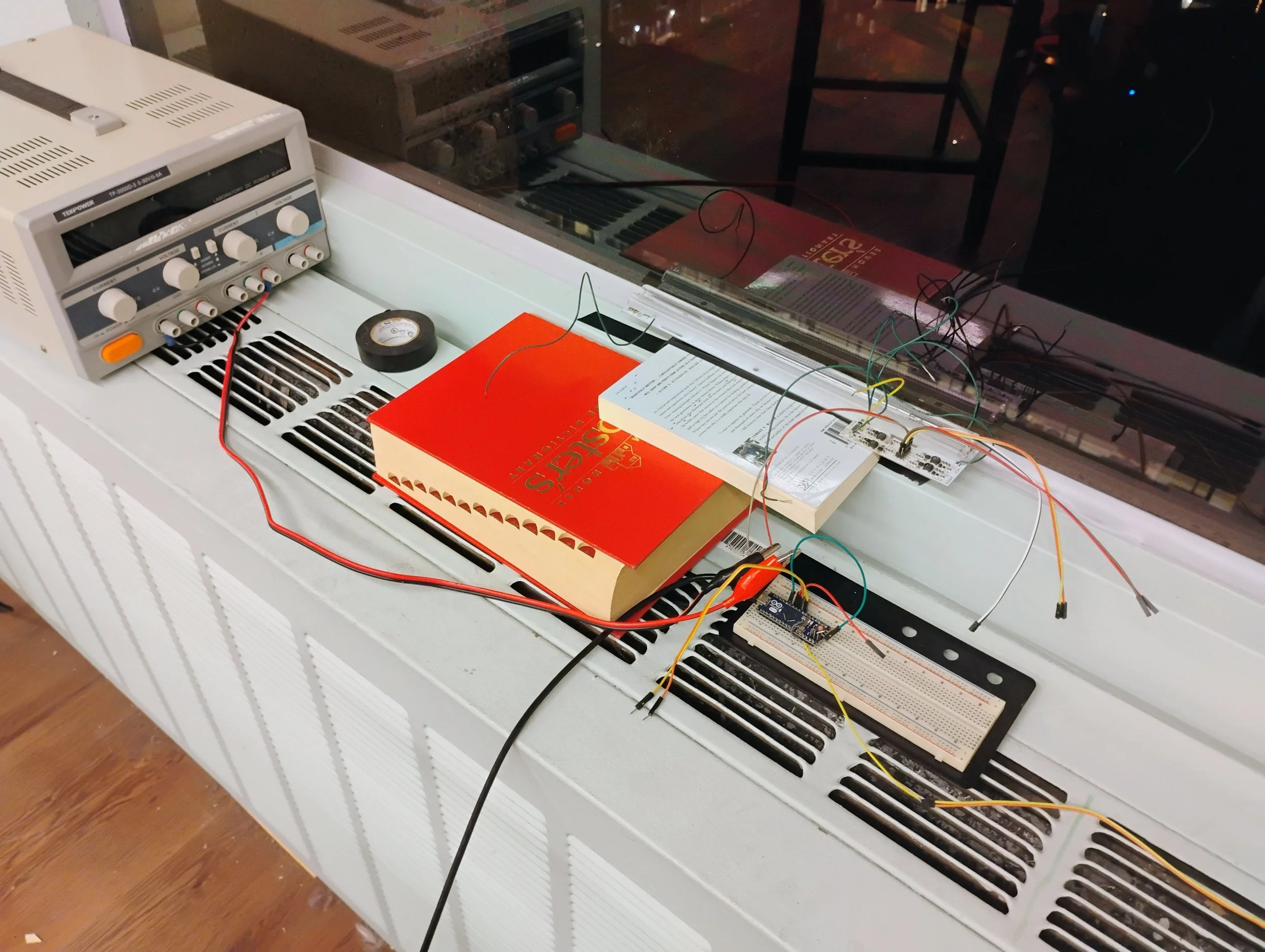
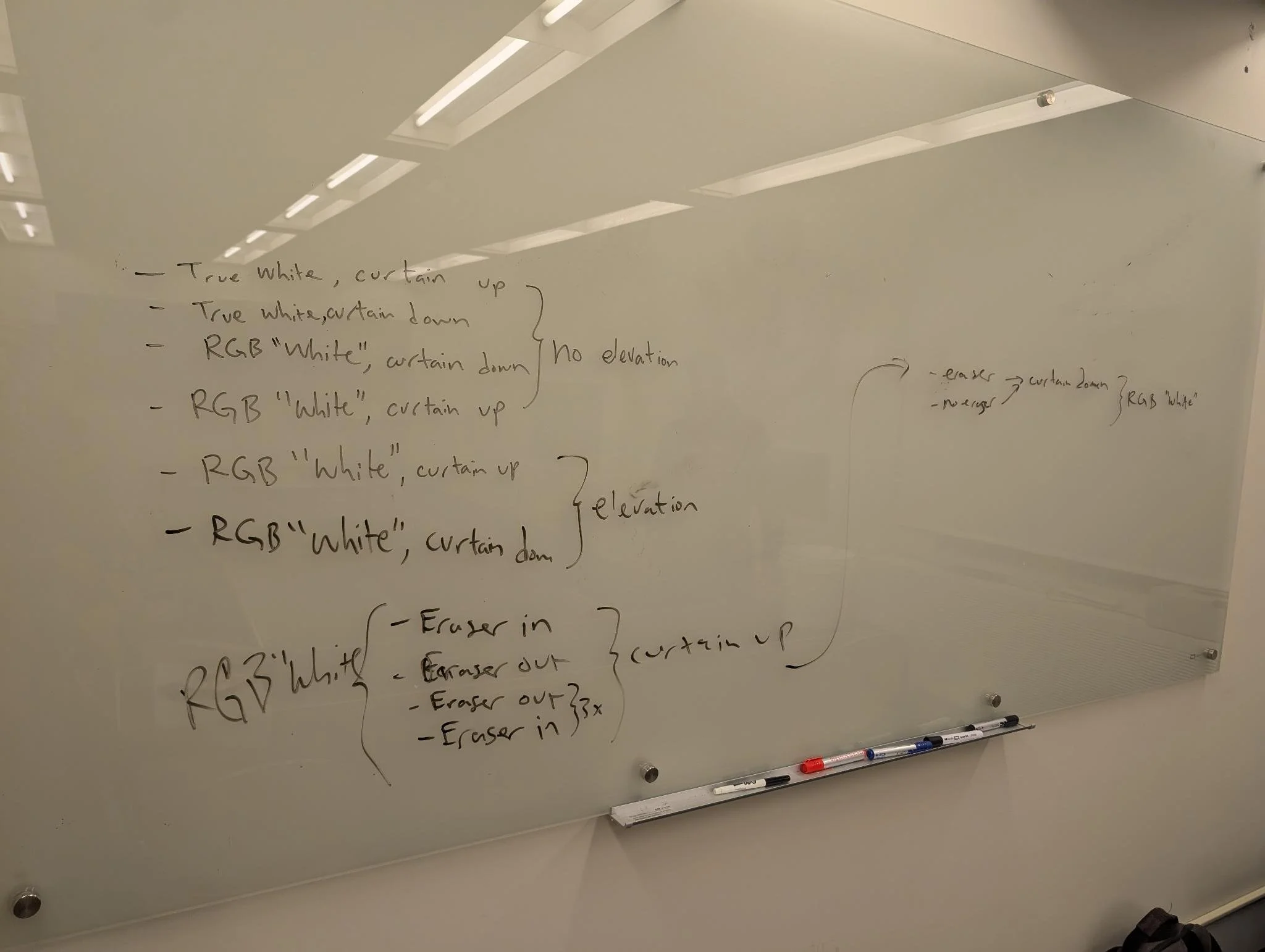
After this test, we settled on using the linear lens with just red, green and blue LEDs, and discovered that the front of the module could be kept opaque without a significant impact on the appearance of the illumination.
V1 Design (December 2025):
Satisfied with the test, I laid out the architecture for the entire system and started designing the electronics.
MCU Board Schematic
LED Board Schematic
During this time other team members also designed and ordered the first machined aluminum enclosure.
One of the things we tried in this first iteration was making our own antennas. We knew we would be making around 200 units (153 windows + lots of spares), and a lot of the off the shelf antennas we found were concerningly expensive. (Around $500 for the total quantity, this was before we knew that would be a small cost in the grand budget of the project. Our original target was under $15K). So I found an off the shelf PCB antenna and we attempted to bootleg it by measuring the dimensions of the copper traces on it and copying the layout. (Making the PCB antennas ourselves would have cost only $35 for the total qty.)
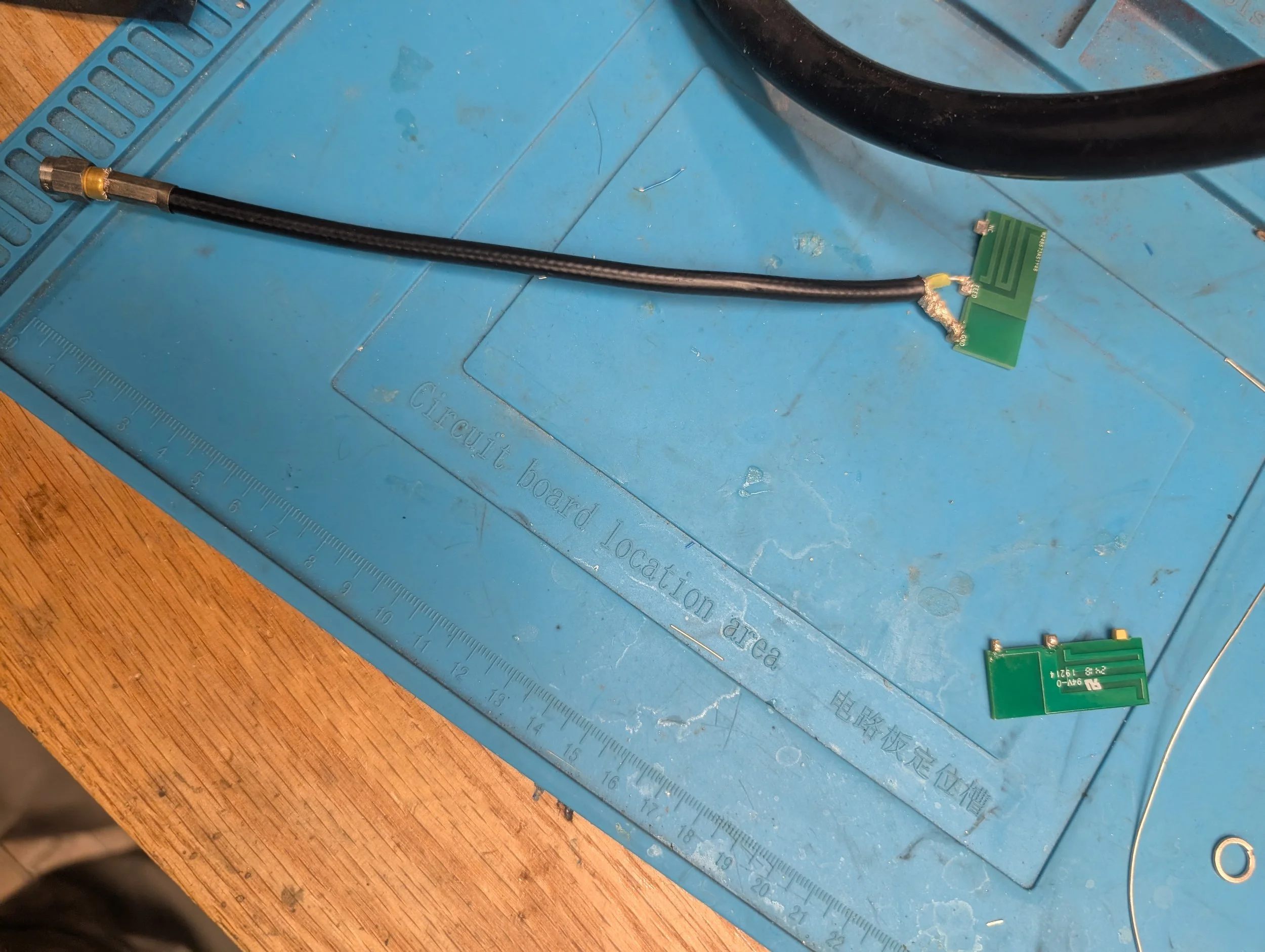
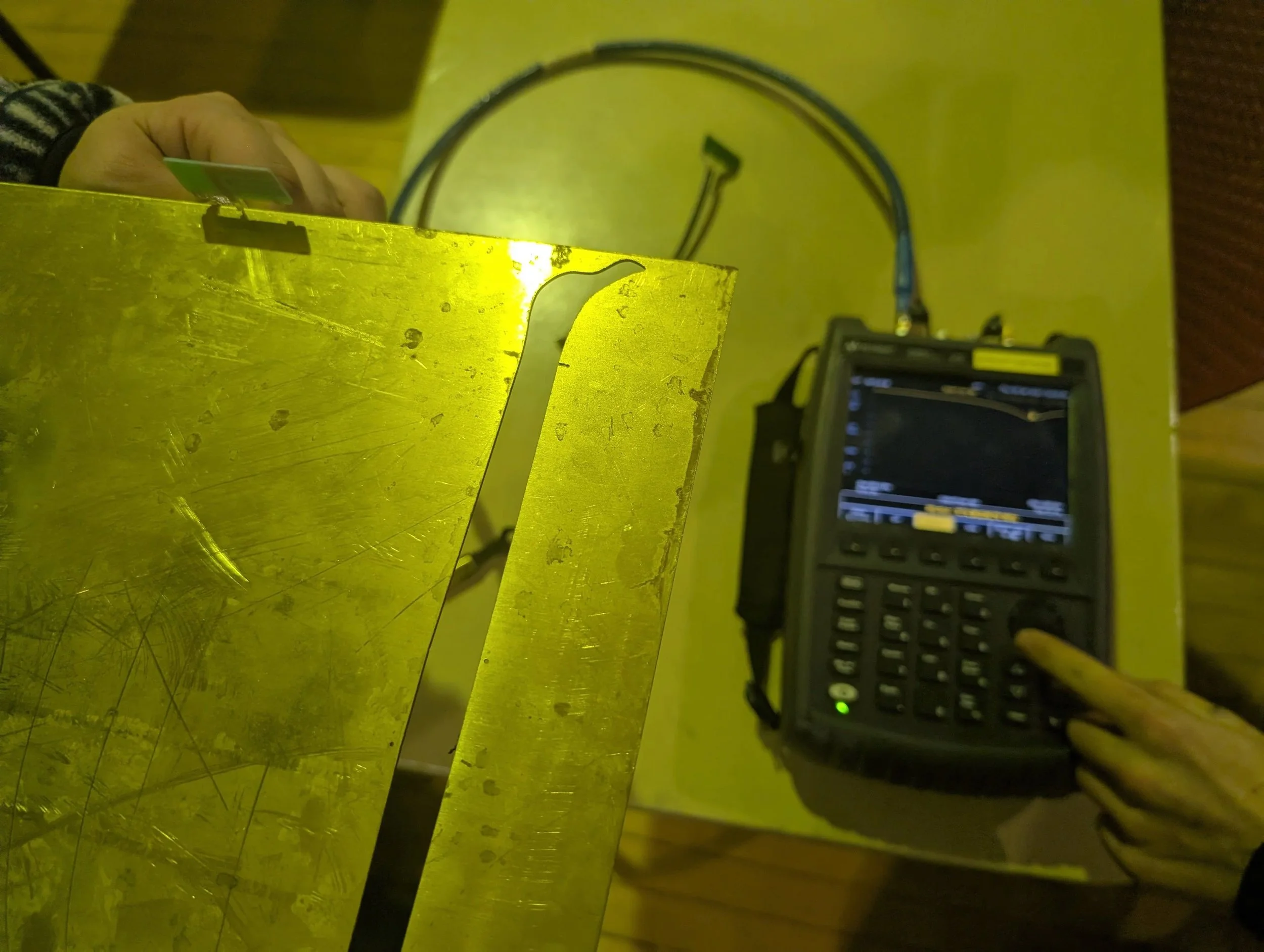
Unfortunately, we were not able to replicate the design closely enough, so we had to abandon this effort. Antennas are extremely geometry sensitive, and we had no simulation capability to refine our replication attempt.
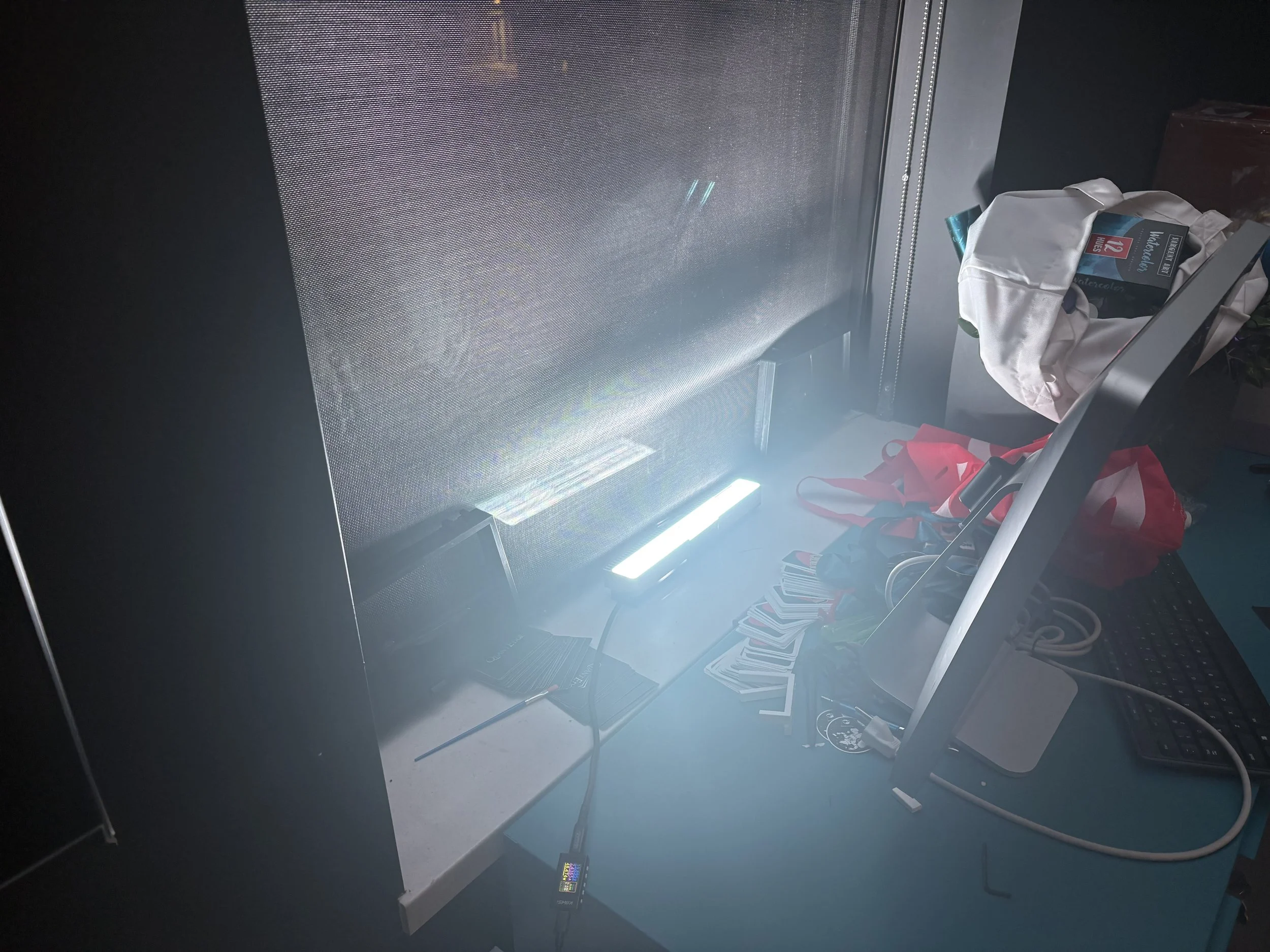
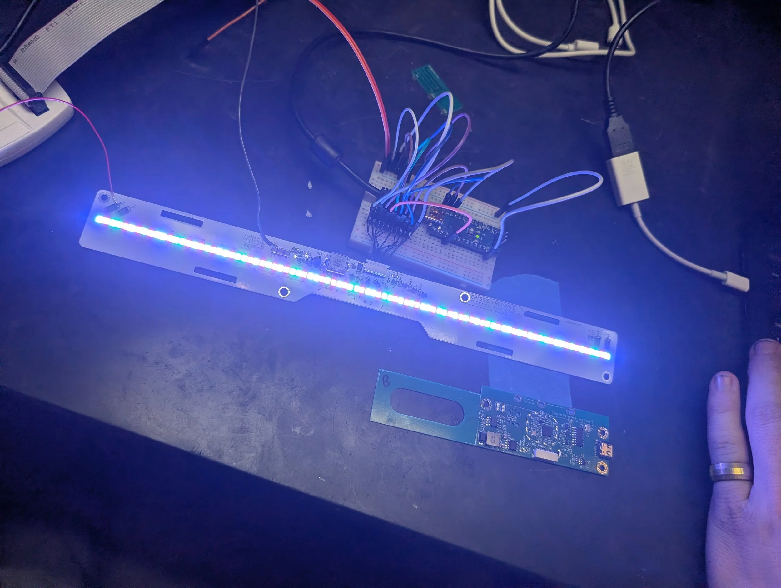
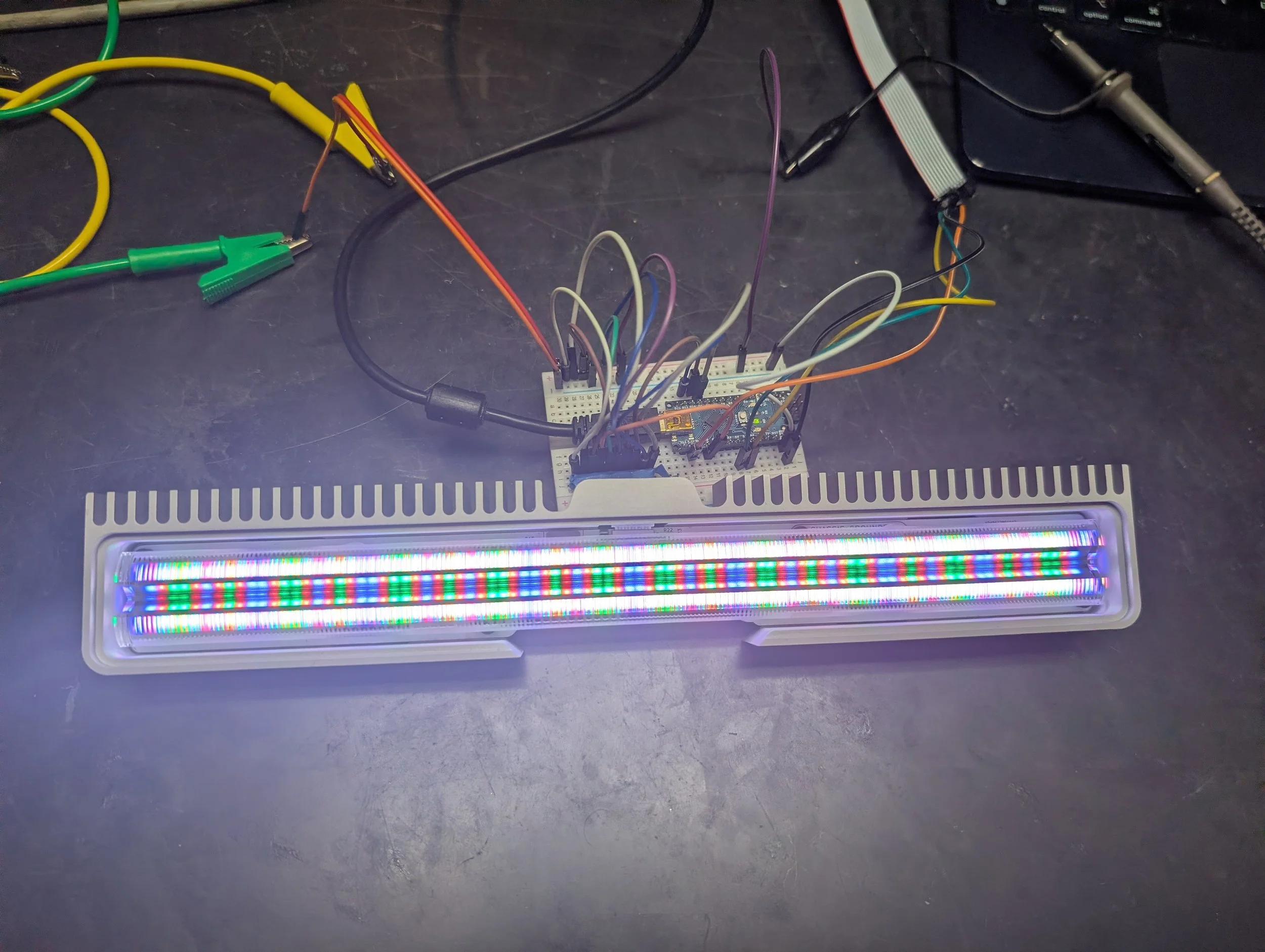
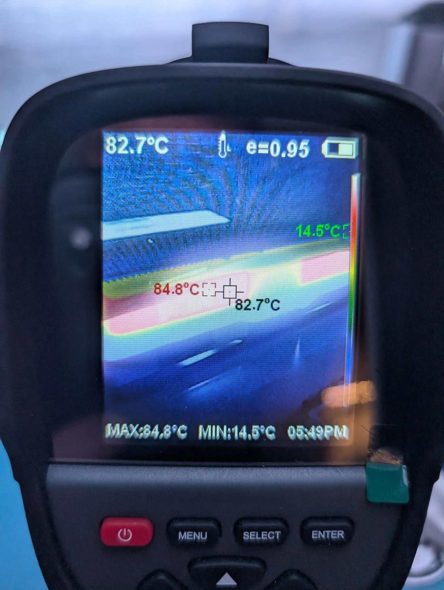
The V1 LED board worked reasonably well and was extremely bright and vivid. It displayed some instability and noise in the boost converter output which necessitated a redesign to improve the layout, but we were able to use the V1 board to do all the testing we needed. It survived thermal testing operating above 80C continuously and a multi-day continuous run to assess its longevity.
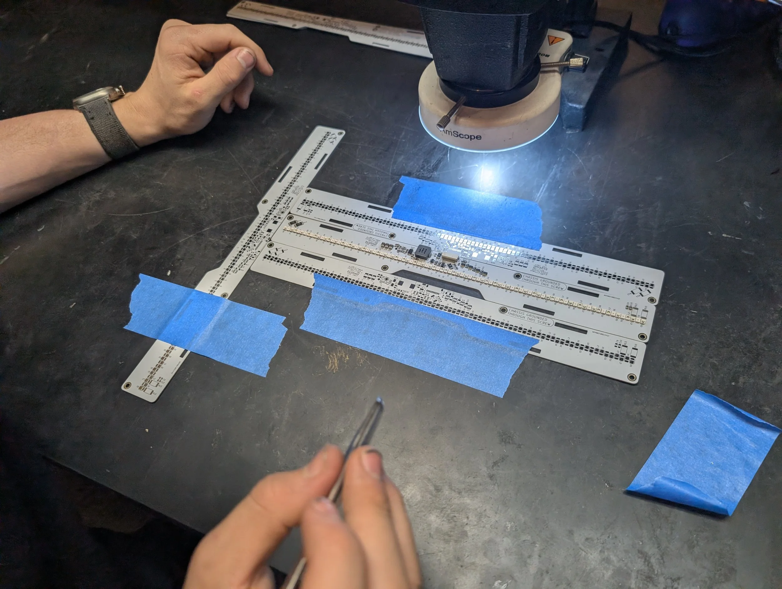
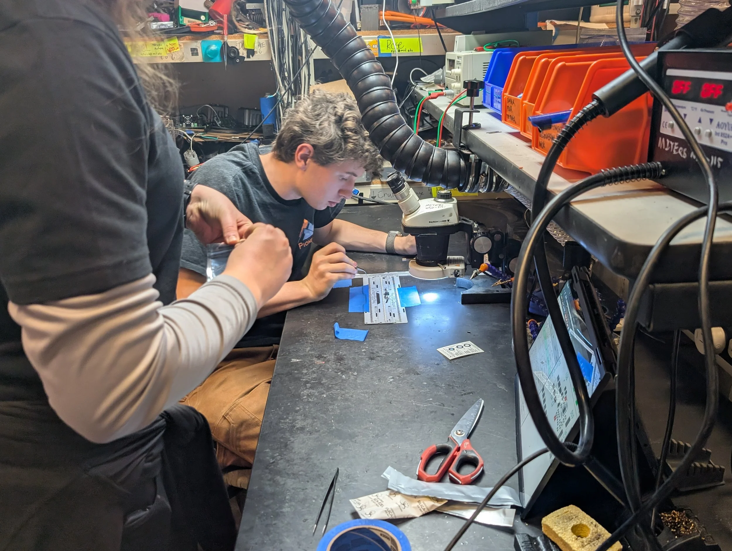
The MCU board had several issues and required 4 revisions before we felt comfortable placing the mass production order for them.
Radio Testing (January 2026)
The Green Building installation runs on 915 Mhz ISM Band FSK radio. The STM32WL33 microcontrollers we are using can operate at a variety of data rates and bandwidths at this frequency, so we had to do a lot of testing to determine the ideal radio parameters to choose to maximize how much data we could send while still maintaining good reception of the radio messages.
We tested the early revisions of the MCU board extensively using a STM32WL33 Nucleo dev board and an off-the-shelf 915 Mhz panel antenna as the base station. We tested all combinations of data rates, 2 GFSK vs 4 GFSK, LNA / PA on the receive / transmit side, spiral antennae vs PCB antennae, etc.
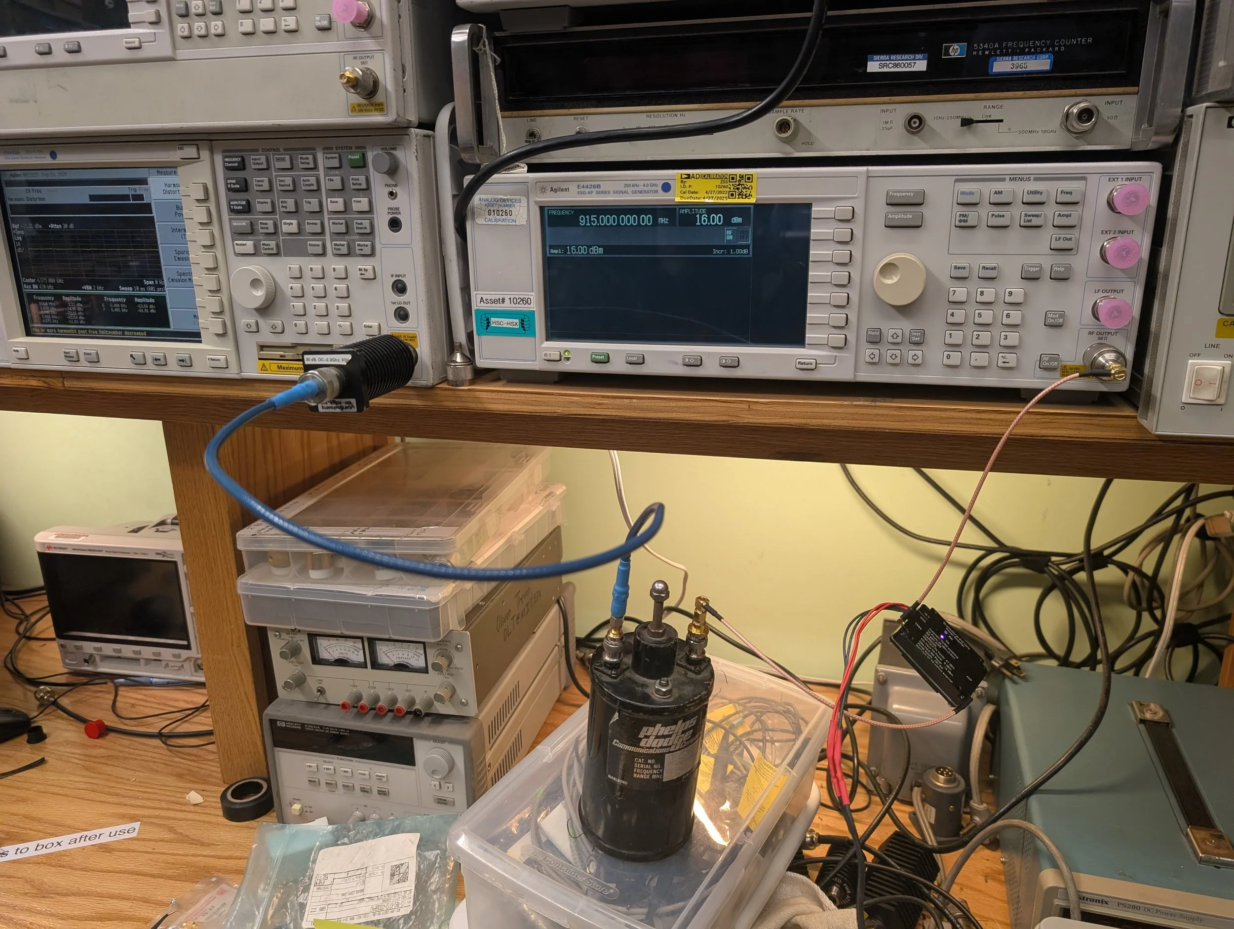
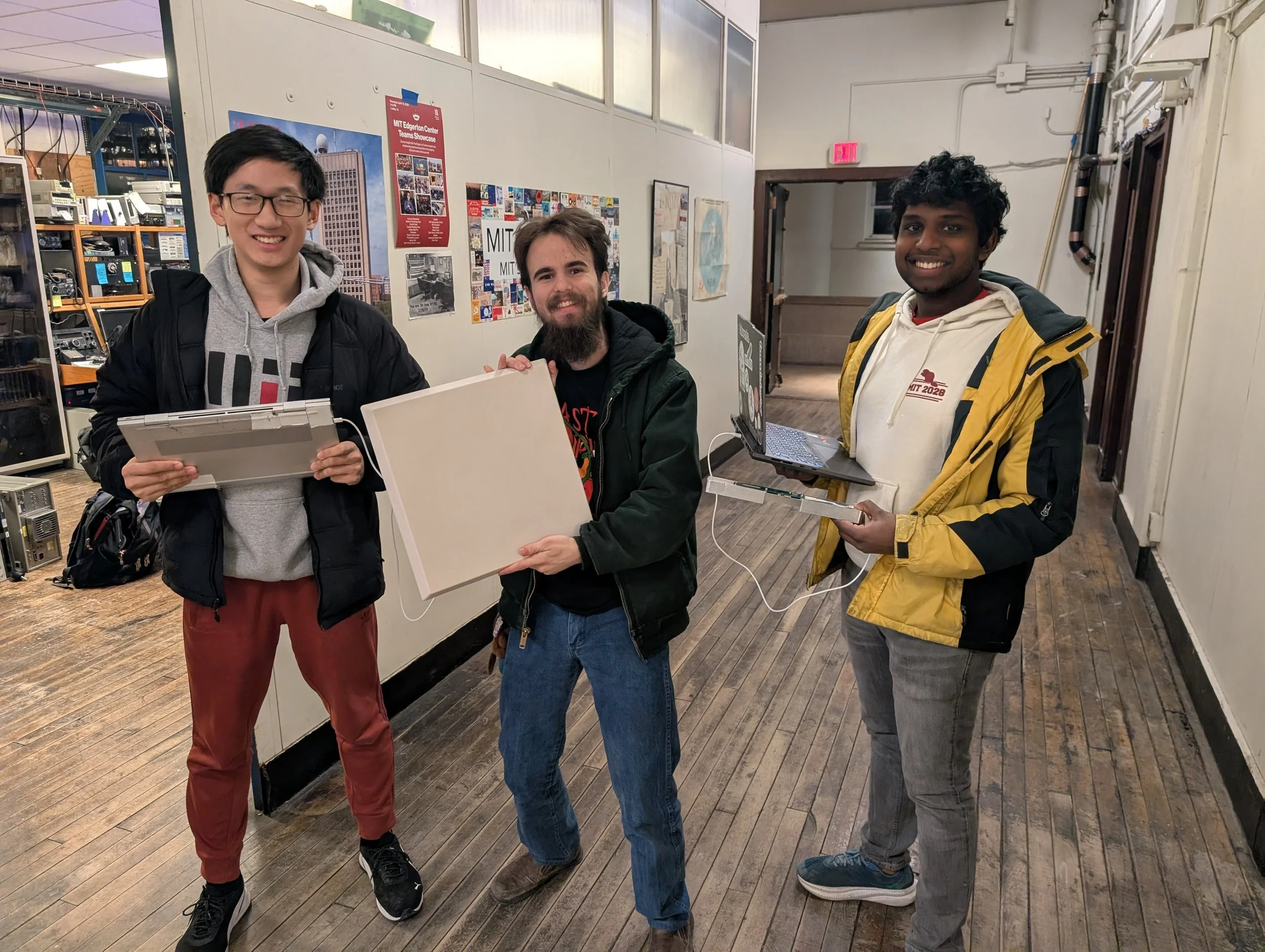
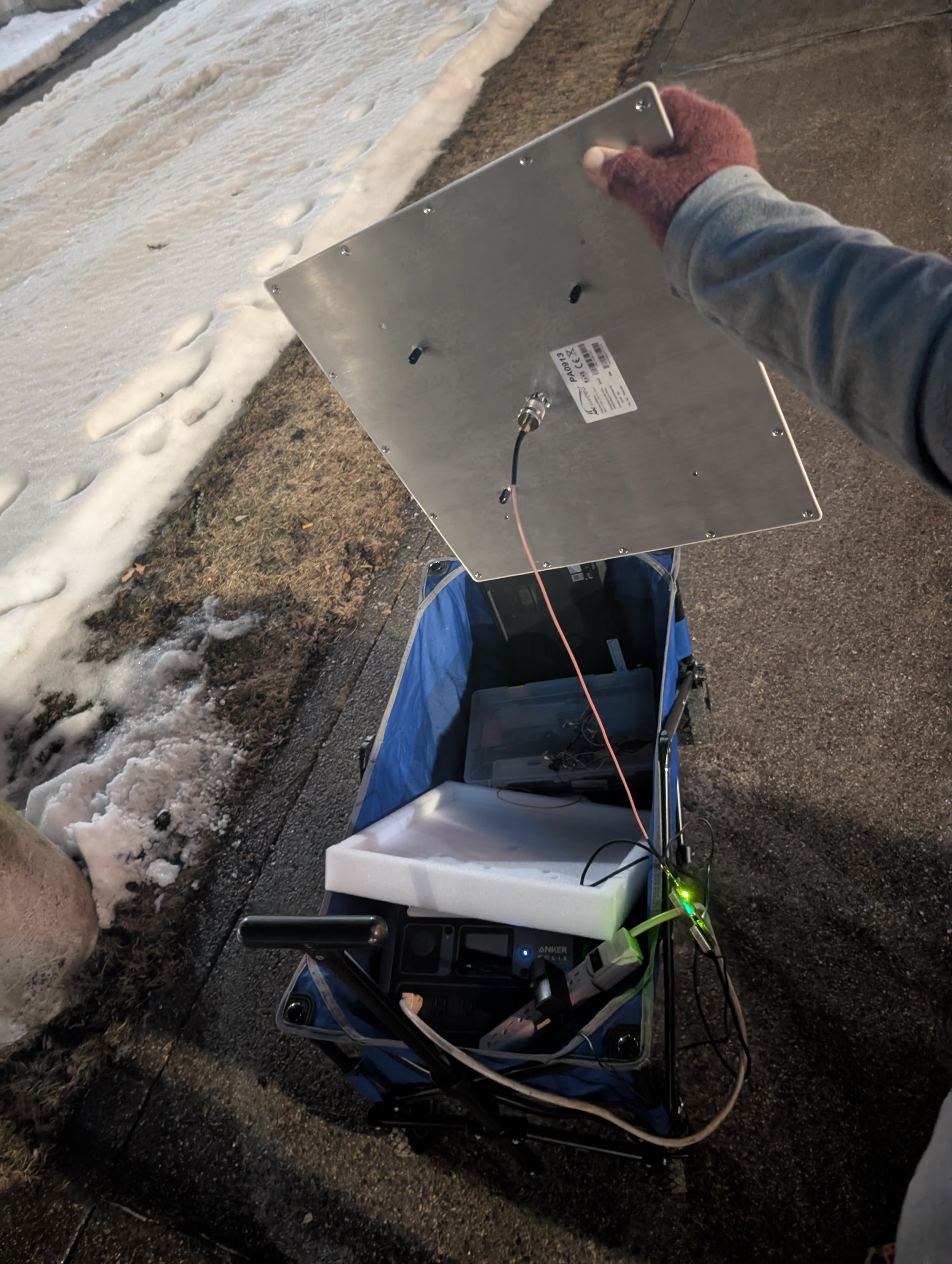
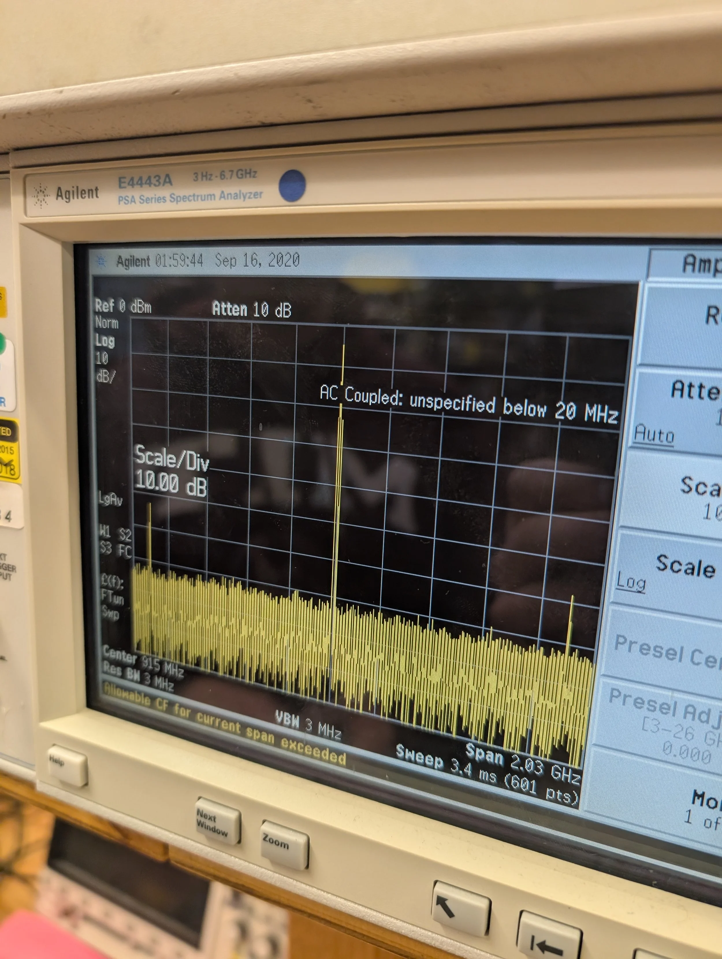
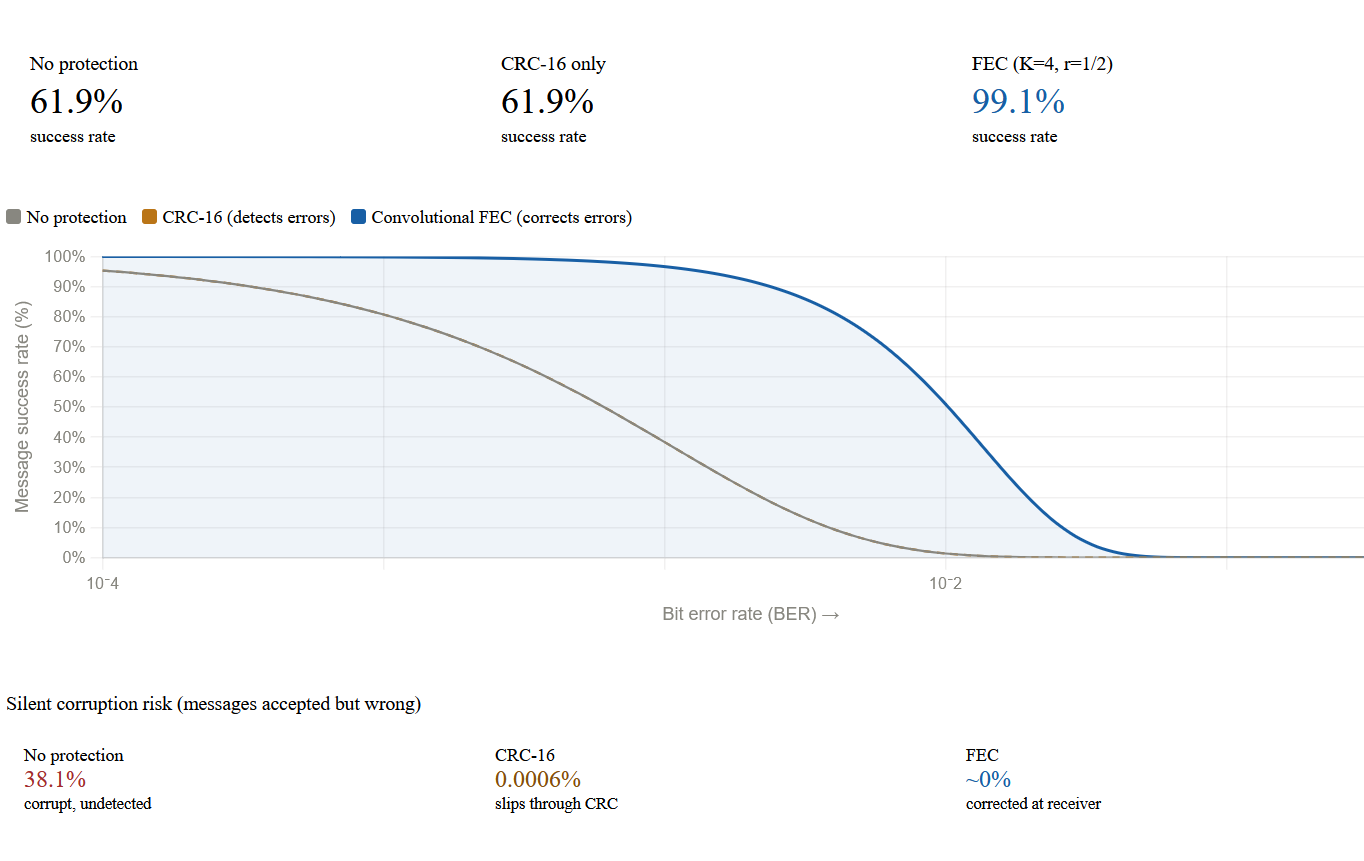
Ultimately we found that the spiral antennae marginally outperformed the PCB antenna, and we could transmit 490 kbps 4-GFSK using a 16bit CRC checksum with the majority of packets being received successfully.
MCU Board Iterations (January 2026)
Over the course of January, I made 4 revisions to the MCU board fixing the RF layout and routing, adding support for the spiral antenna, improving the USB programming circuit, and resolving other issues encountered during testing,
LED Board Iterations (January 2026):
During this month I also revised the LED board, improving the layout of the boost converter considerably.
Enclosure Iteration (January 2026):
Finally, we also finalized the design of the aluminum enclosure, adjusting the button type and placement, fin spacing and depth, cable routing channel and screw hole placement.
Placing orders (February 2026):
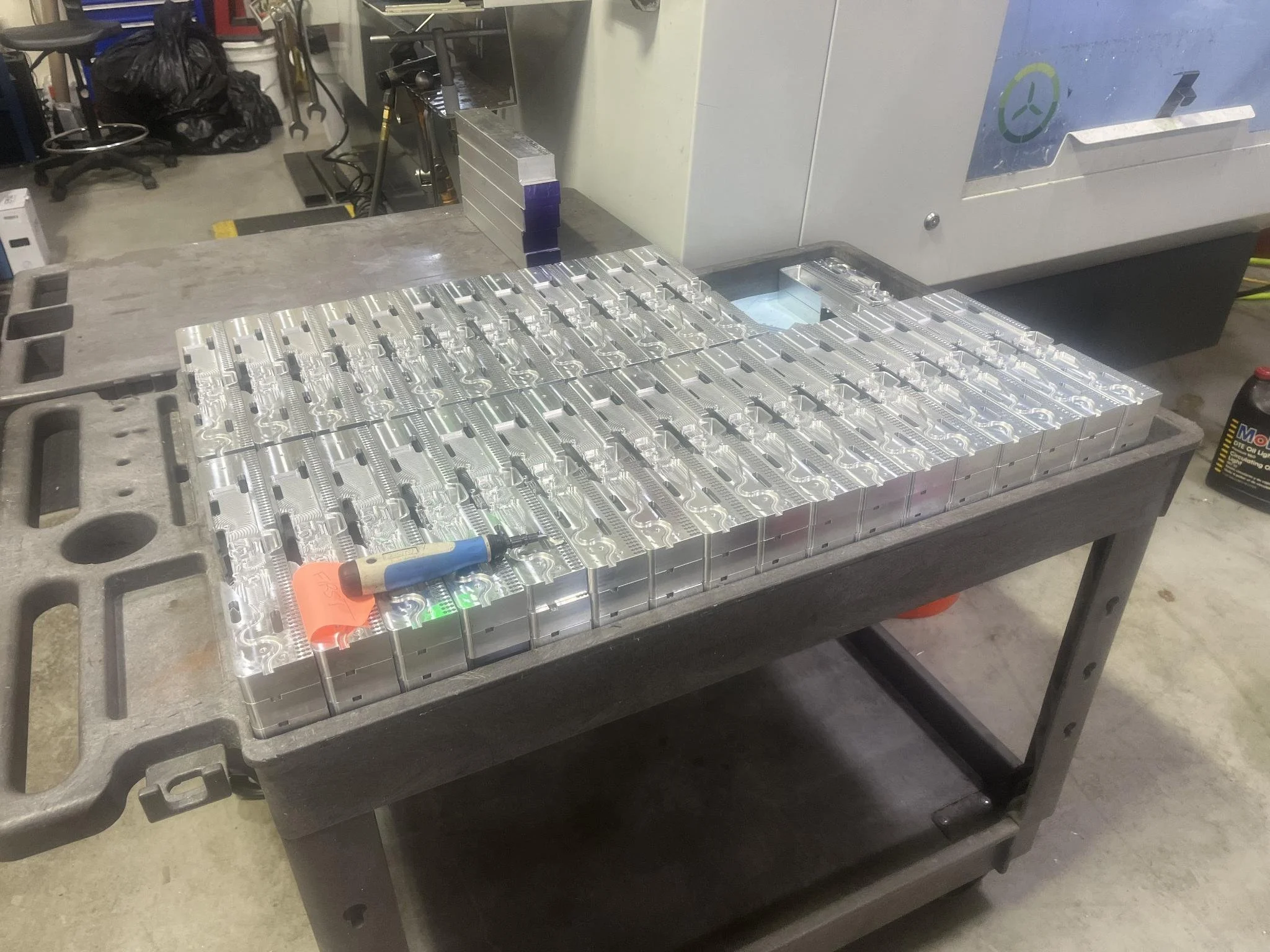
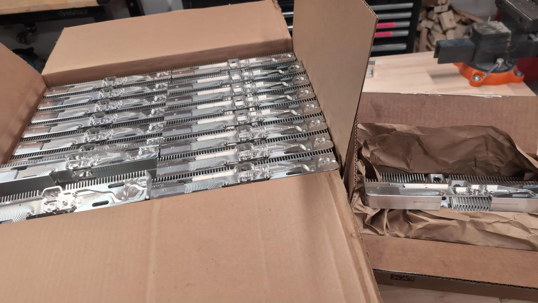
Once we were confident in our design, we started working out how to source all the parts involved. A major concern of ours was sourcing the aluminum enclosures, given parts like those are explicitly covered by large tariffs. Additionally, the combined weight of all 200 pieces would make air shipping very expensive, and shipment by sea would take a very long time. Finally, Chinese New Year would take place right in the middle of our procurement period, creating a 2-week gap when no orders would be produced. After a lot of searching for Mexican CNC shops (with low tariffs), Chinese shops that would quote us a low enough price despite tariffs, and US manufacturers that could potentially offer us a sponsorship, we finally found a local machinist (Cantrell Machine) through the MITERS network. He gave us an extremely good price, and since he was in Massachusetts we did not have to worry about tariffs and he could drop the parts off himself without us having to pay for any shipping.
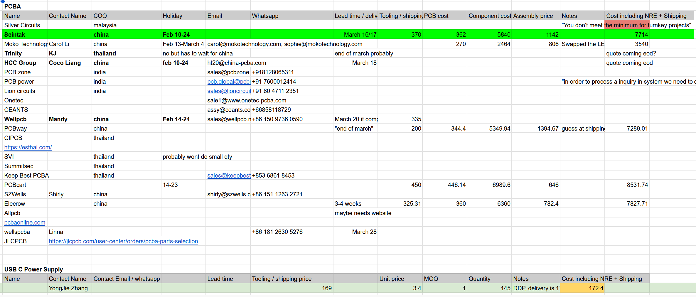
For the PCBs, there was no way to avoid Chinese manufacturing. During the design process, I had selected almost entirely Chinese origin parts to reduce the BOM cost, and Chinese board houses were able to source these parts effortlessly and produce boards for us at an extremely low cost with excellent quality. We settled on Scintak as our supplier for turnkey service fabricating the boards and soldering the components on them.
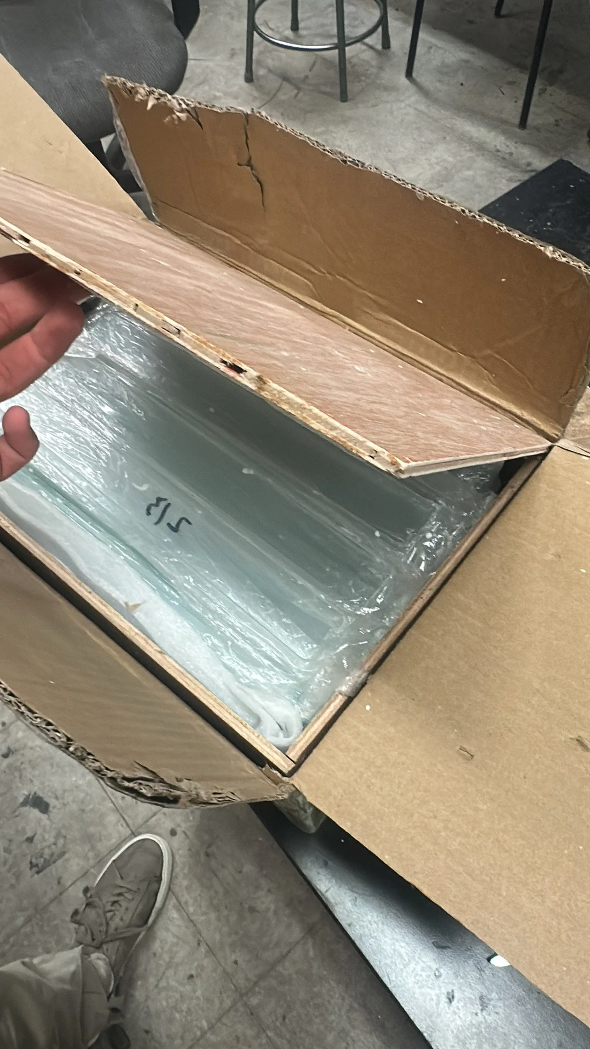
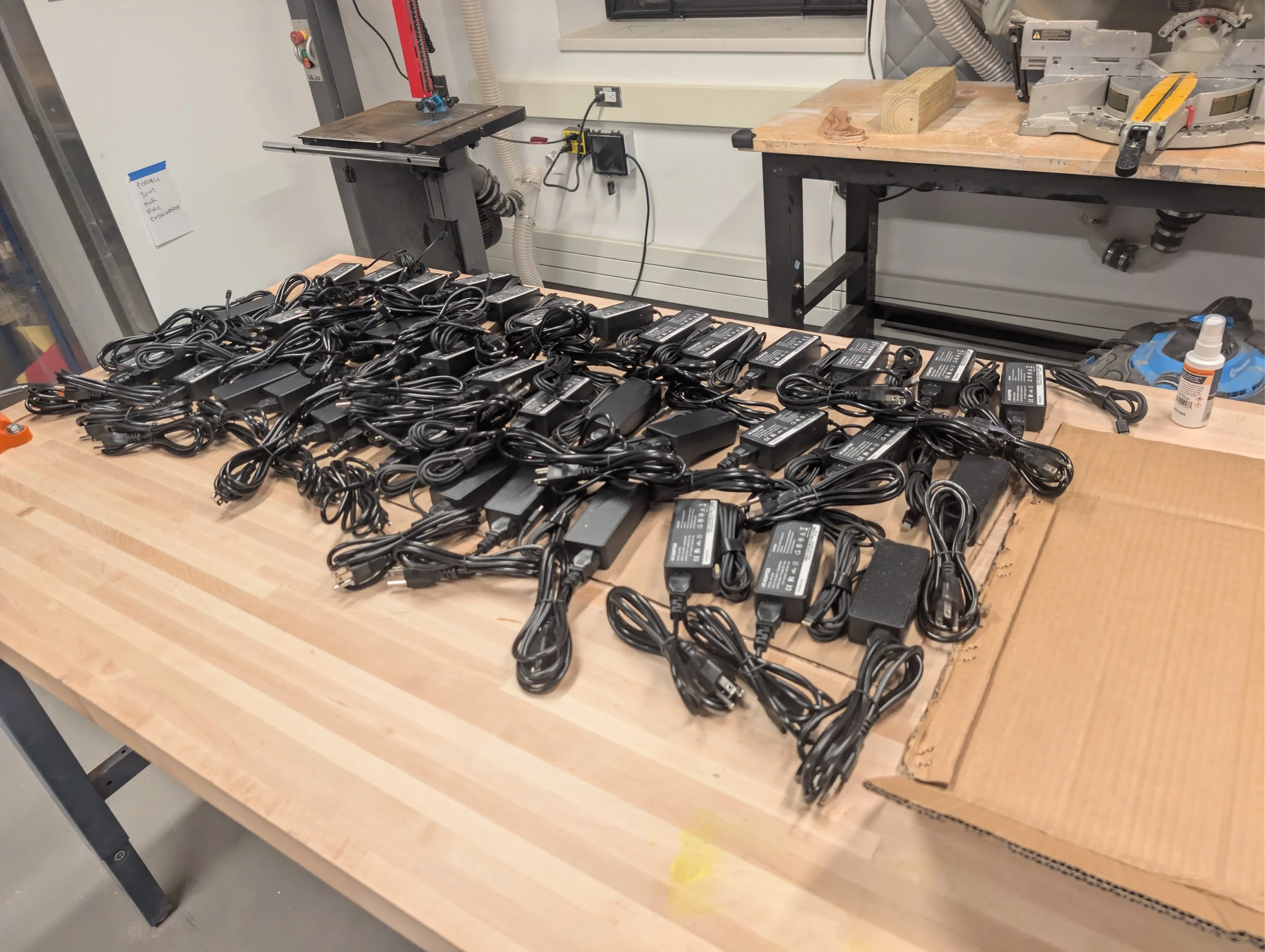
While I negotiated the orders for these custom components, I also had a group of students placing wholesale orders on Alibaba for all the off-the-shelf parts: glass panels, power supplies, buttons, cables etc. Almost all our parts came from China to keep our costs as low as possible.
Base station (February 2026):
While all our orders from China were coming in, we focused our development efforts on the radio base station.
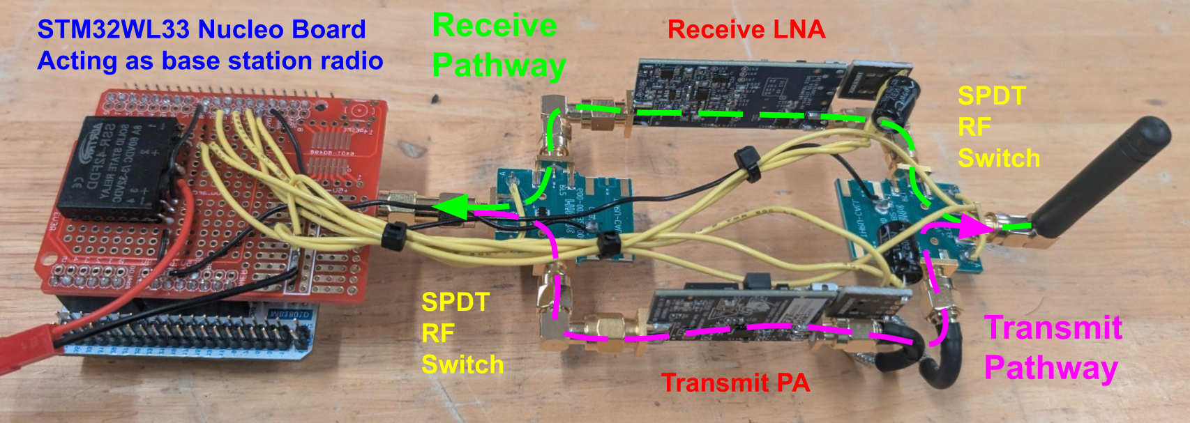
In our radio testing we found that amplifying the radio signal dramatically improved our reception. However, we did not want to include any amplifiers in the window modules, since that would complicate the design on the circuit board (which did not have space to fit too many more components), introduce more failure points and increase the cost. So, all the amplification was done on the base station side, both along the transmit and receive pathways.
In order to speed up the development time, I did not make any PCBs for the base station, instead keeping everything modular by using off-the-shelf development boards for all the RF components. Bidirectional amplification was achieved by having both a PA and LNA with two SPDT RF switches so either amplifier could be inserted into the signal path based on whether the microcontroller was transmitting or expecting to receive a message.
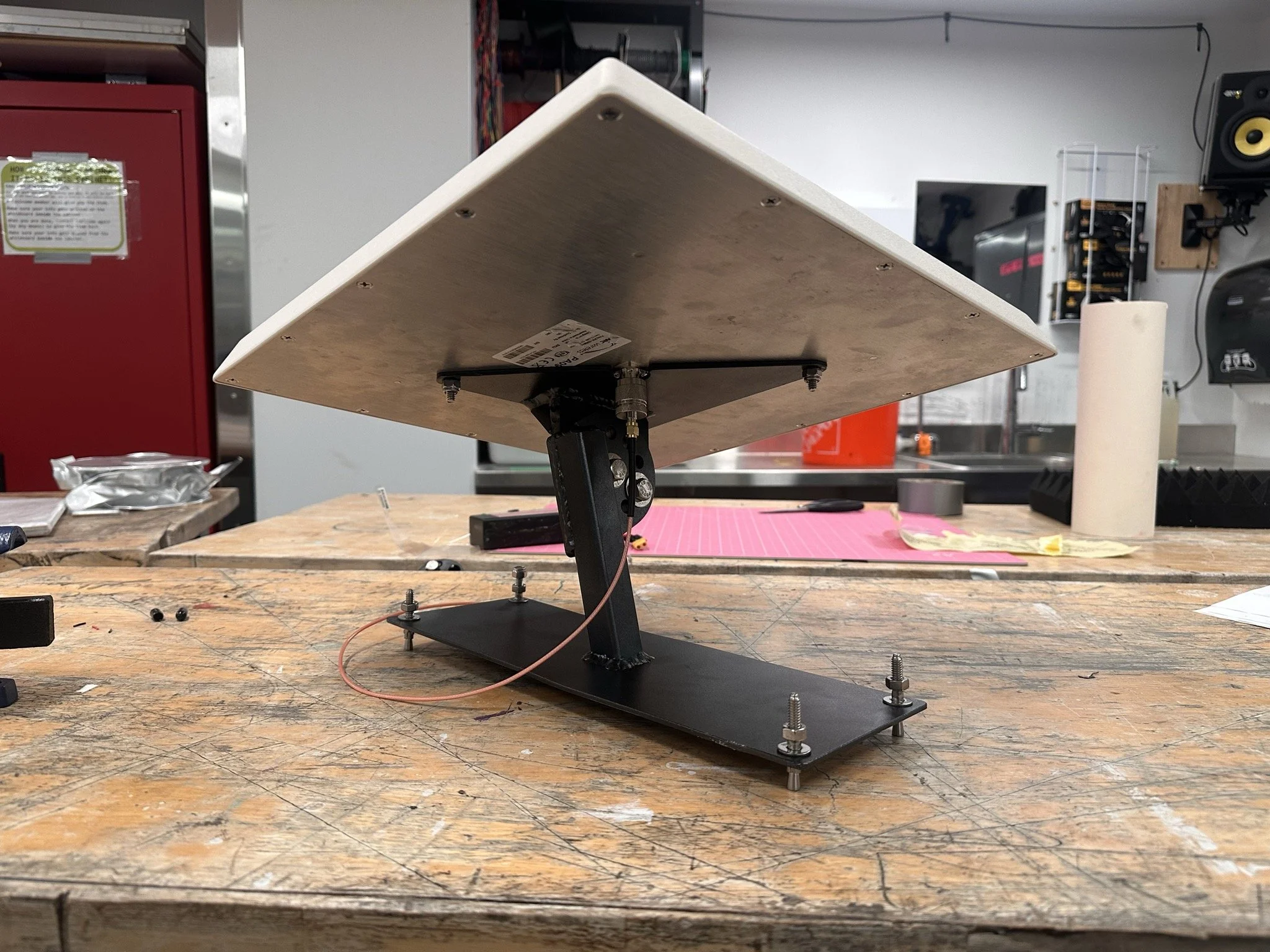
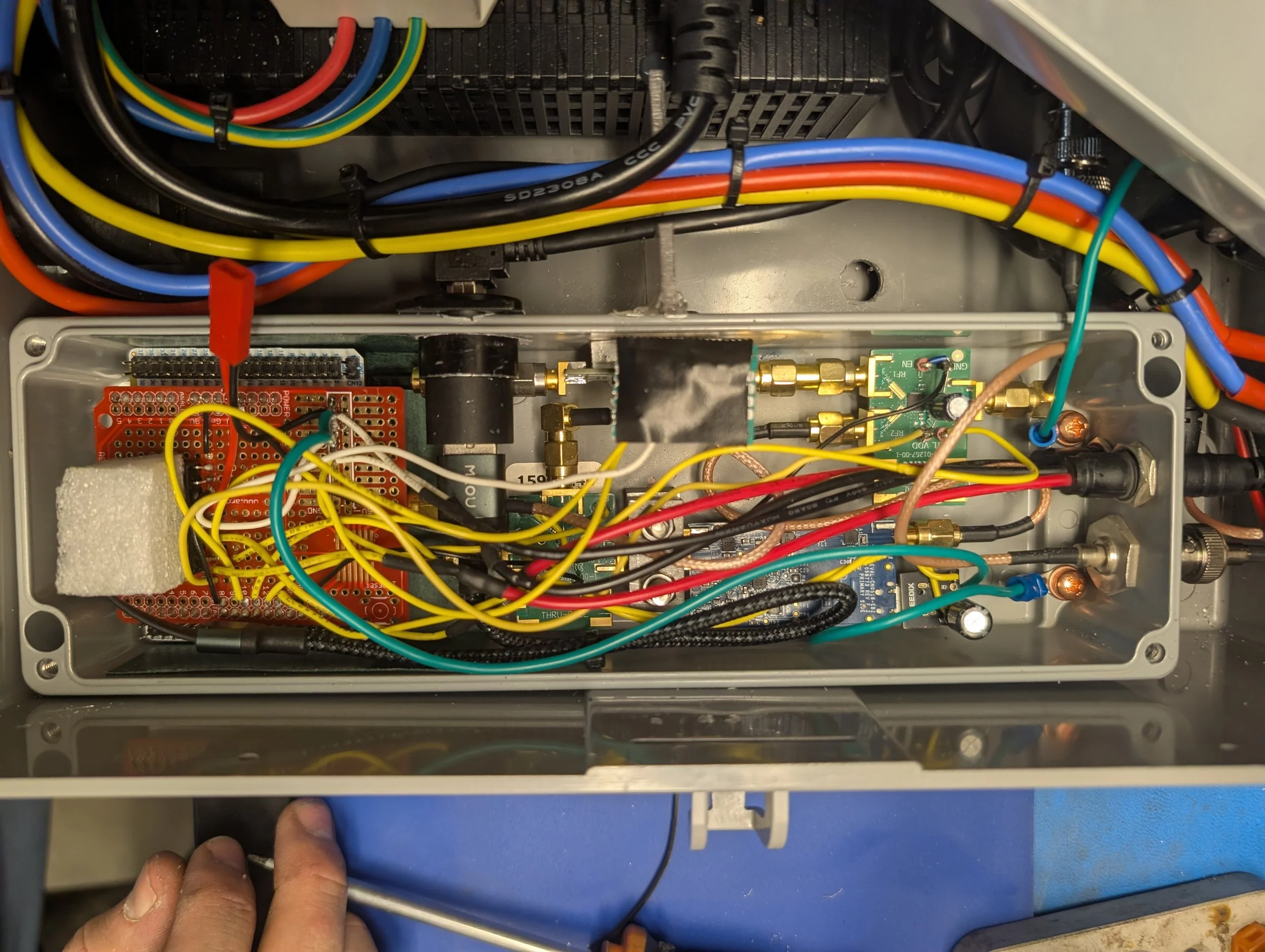
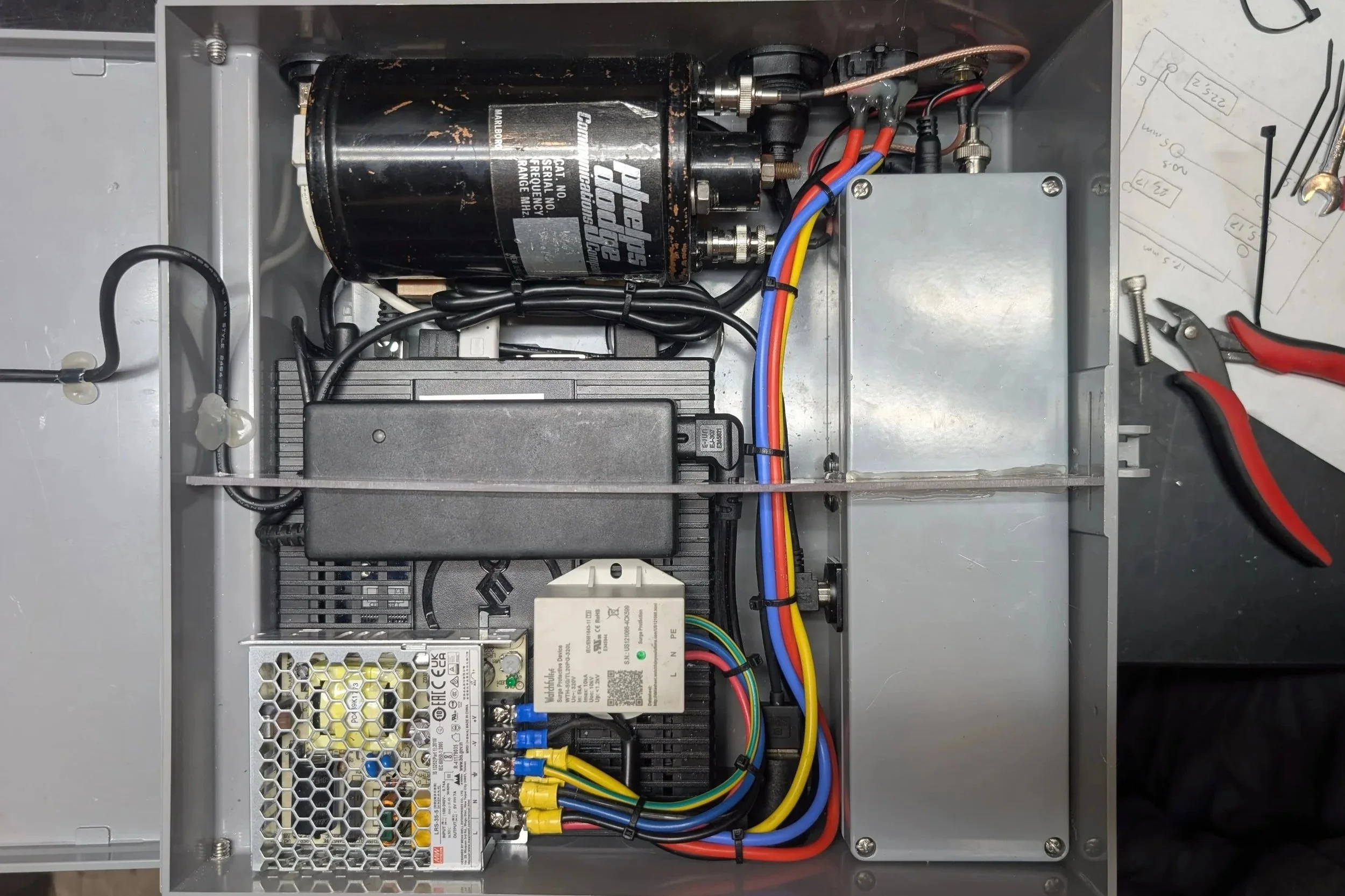
We also installed a 915 Mhz cavity filter to eliminate any harmonics from our transmitted signal to ensure we did not cause or receive spurious interference when operating the display. The entire radio system was packaged in a robust sealed aluminum enclosure with custom aluminum pieces I machined to internally mount everything. I also welded up an adjustable mount for our antenna.
Software development (February / March 2026):
I was not directly involved with writing any of the software for the project, but I laid out the overall software architecture for our system and plan our all the details of the radio communications.
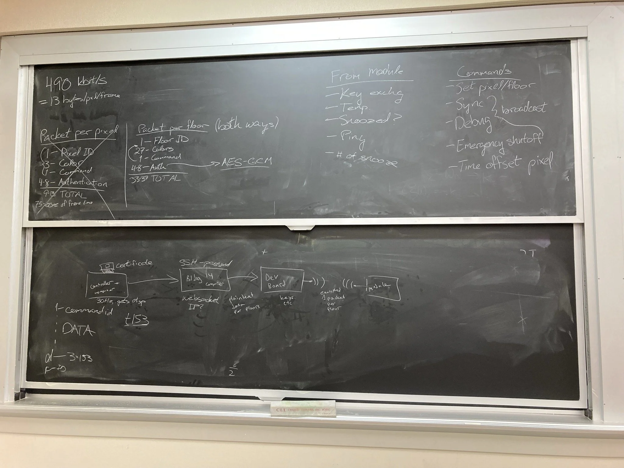
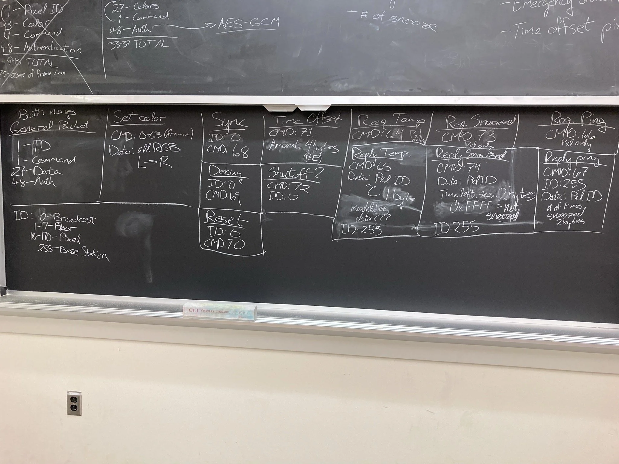
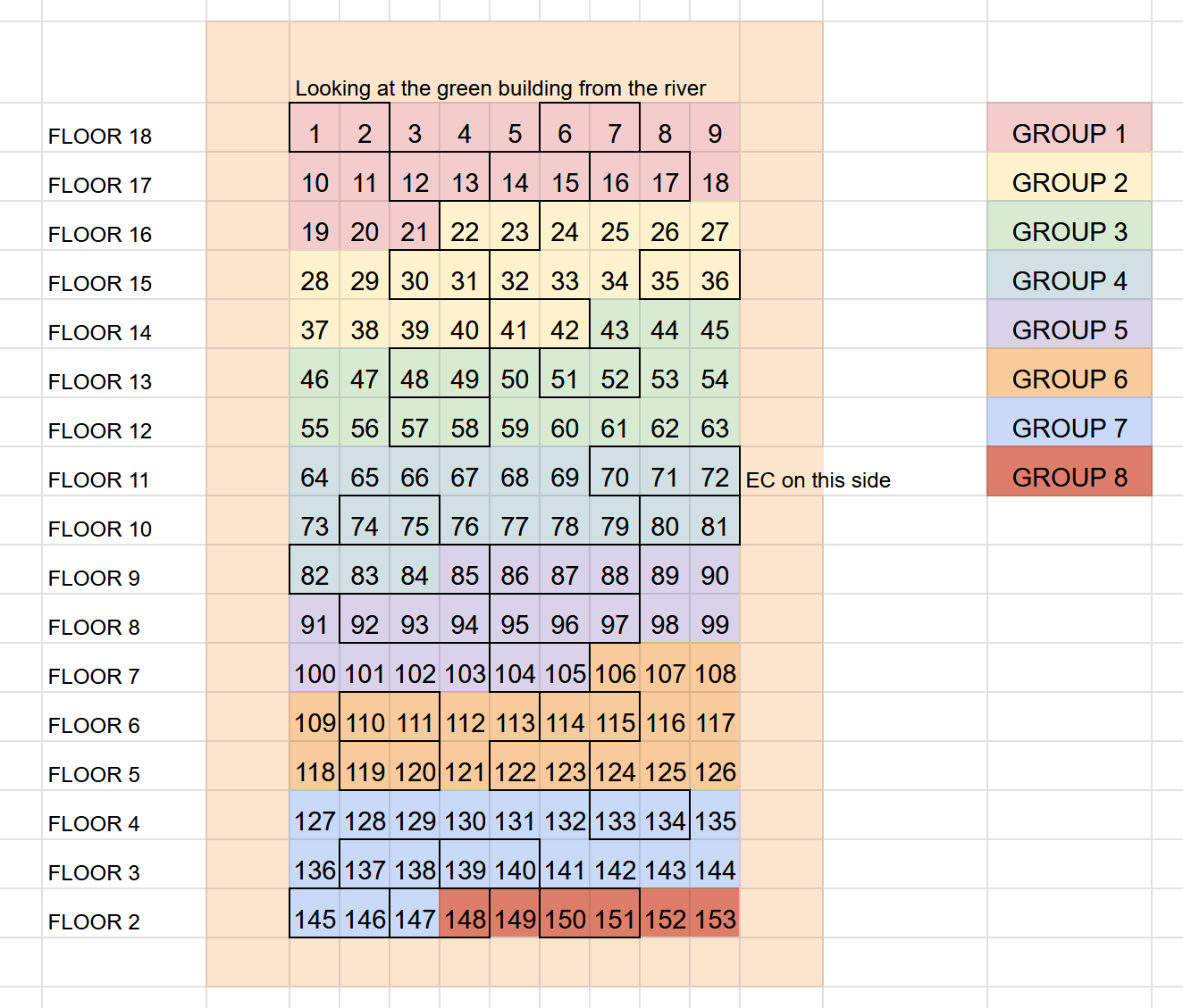
We created our own radio protocol with custom packets to transmit chunks of frame data. We kept the packet sizes as small as possible and each packet is transmitted with an error correcting checksum to ensure that even if a few bits got corrupted over the air, the microcontrollers can still recover the data, or recognize if a message was too garbled and ignore it. Additionally, all of our radio communications are encrypted with military grade 128-bit AES-GCM. Whenever we go to operate the installation, the base station goes through an unlocking and key handoff procedure with each module, generating a one time passcode to encrypt that session’s messages. All the firmware on our microcontrollers is read-protected and we never transmit the same key more than once. Given the installation is visible throughout Boston, we needed to implement strict security features to ensure that no one can hijack it and display unsavory messages that would prompt the MIT administration to force us to take everything down.
Production hardware fixes and testing pre CPW (March 2026):
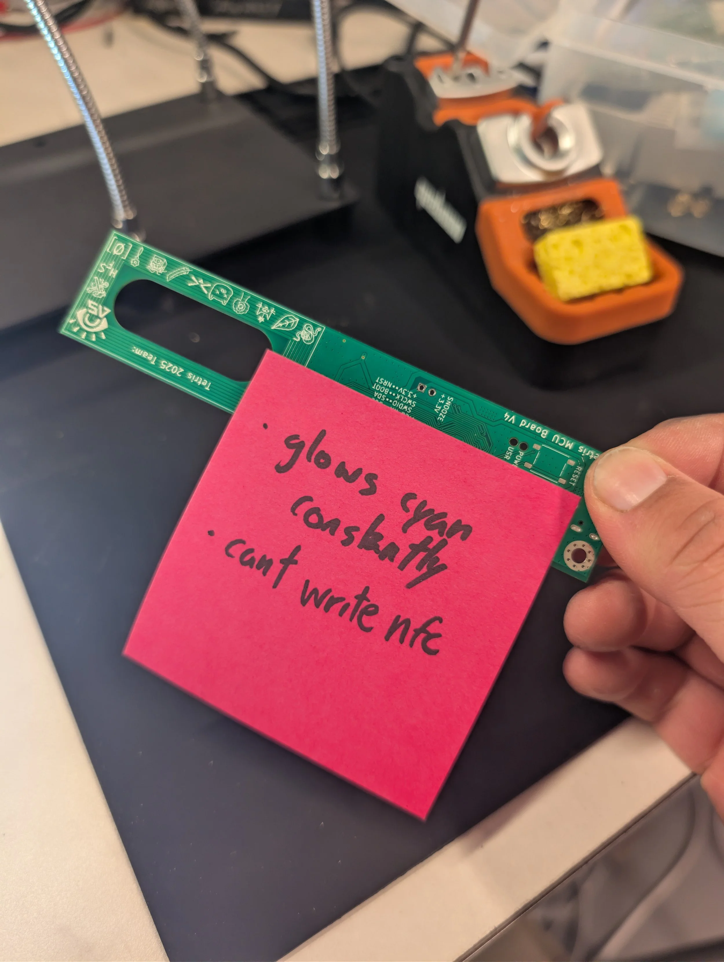
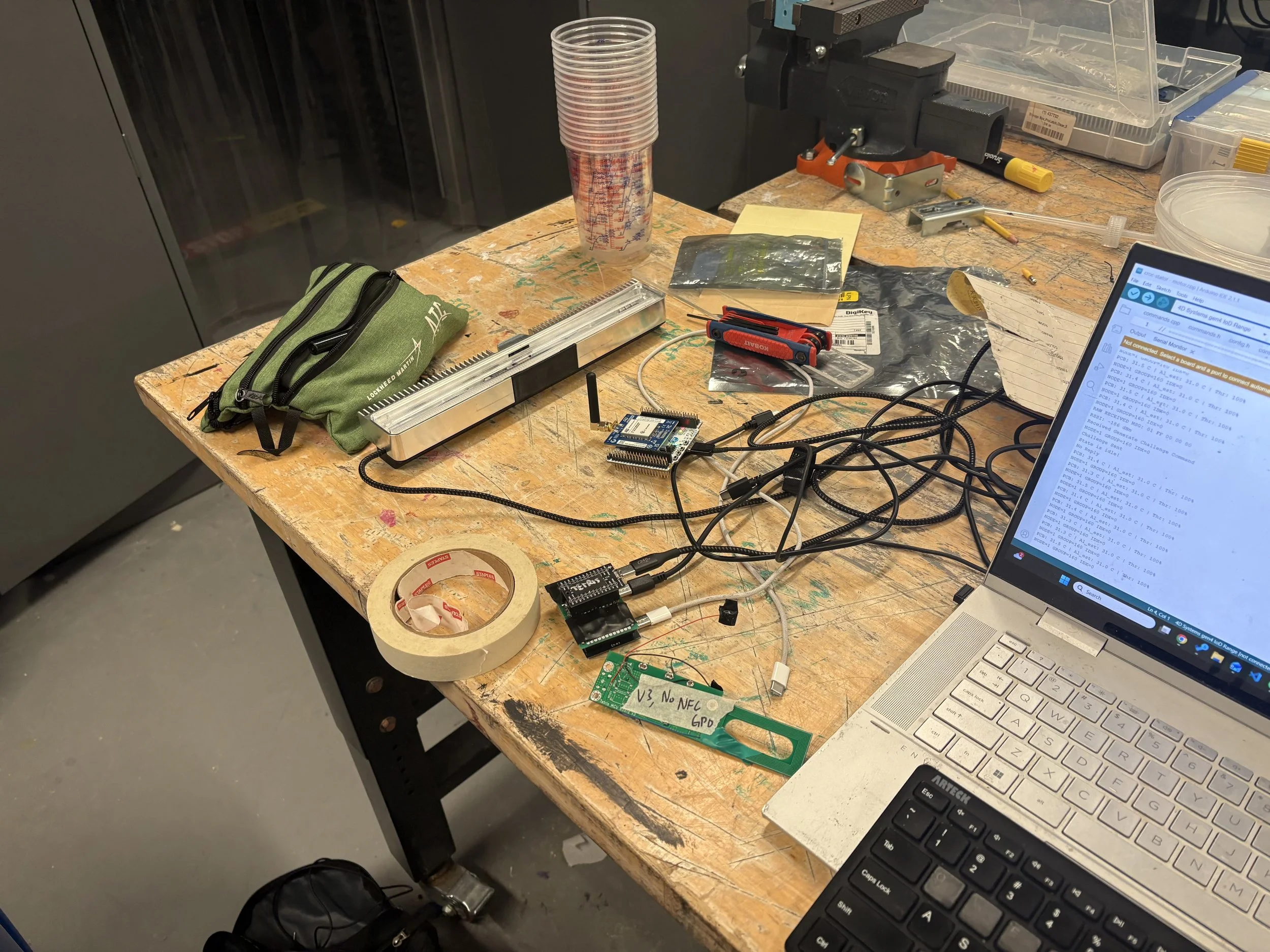
While we were waiting for the final boards and enclosures to come in, we continued to test the prototype boards we did have, and discovered a few issues that were present on the production hardware, meaning we would have to make some bodges on all 200 units.
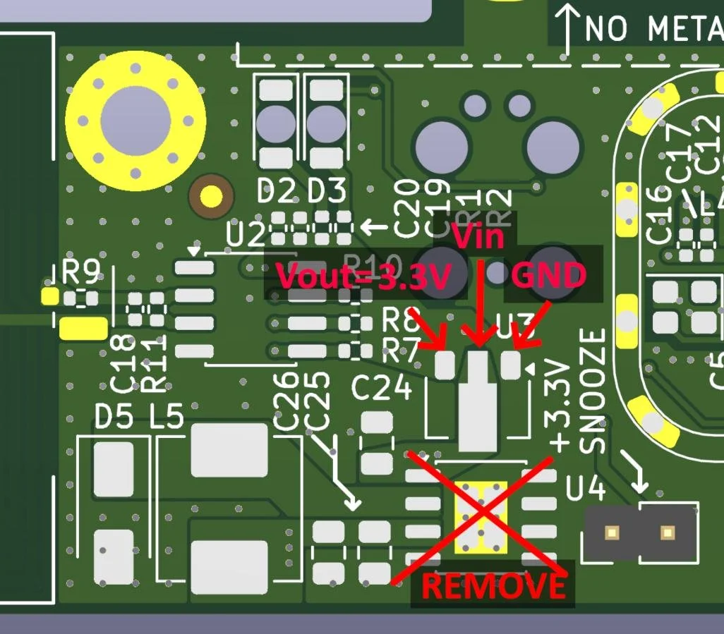
The voltage regulator on the MCU board:
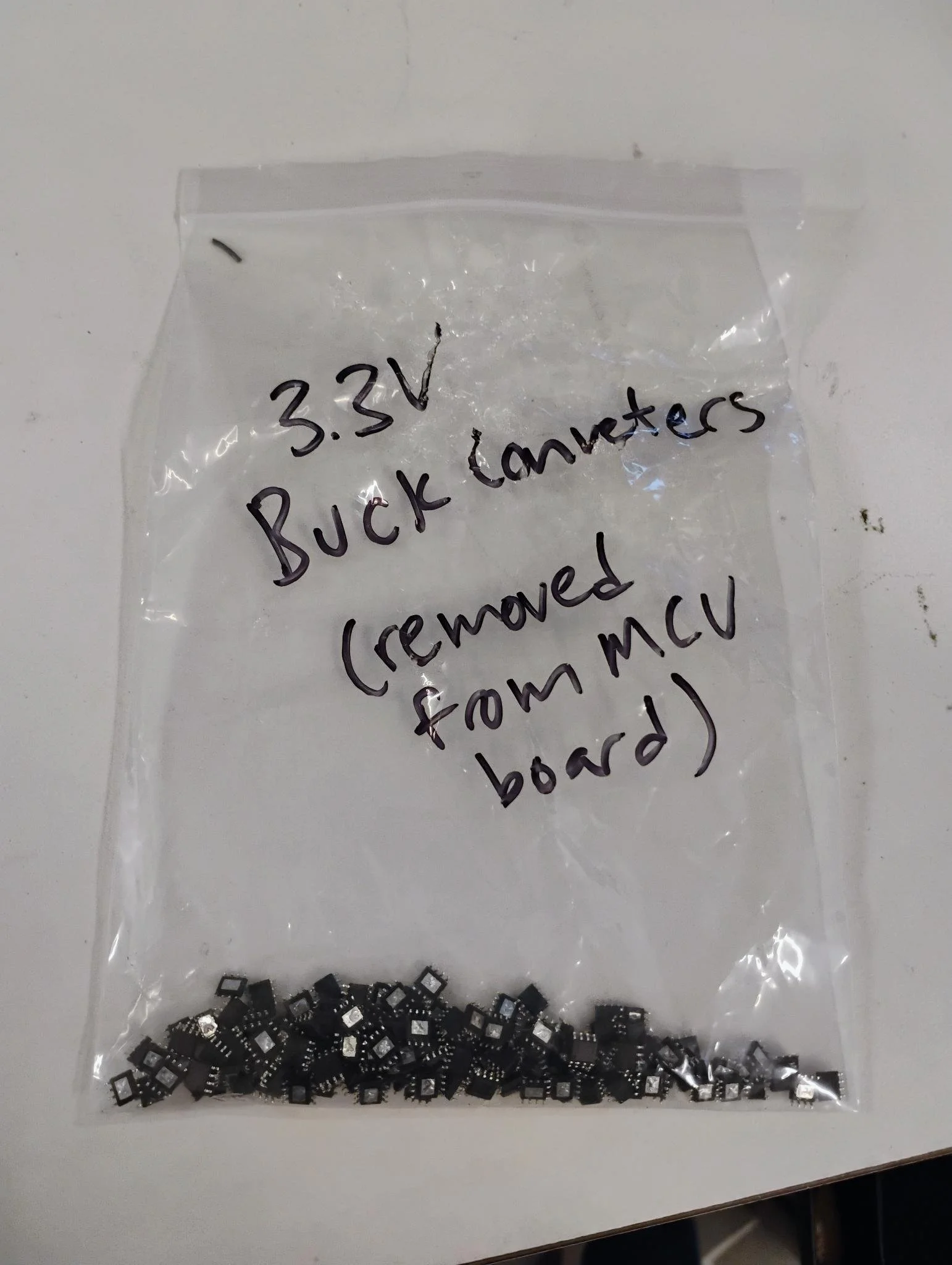
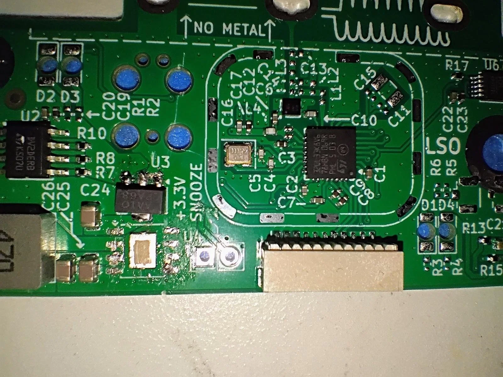
Until this point, we had done all of our testing powering the MCU board from the 5V bus voltage supplied by a laptop USB port. The MCU boards were designed with a buck converter to step the input voltage down to 3.3V for our microcontroller. However, in the production units, the USB C PD power supply would deliver 20V to the MCU board and the LEDs. We found that when the buck converter was made to step this higher input voltage down to 3.3V, it introduced a lot more switching noise on its output, which ended up being too noisy and interfering with the microcontroller’s ability to receive a clean radio signal.
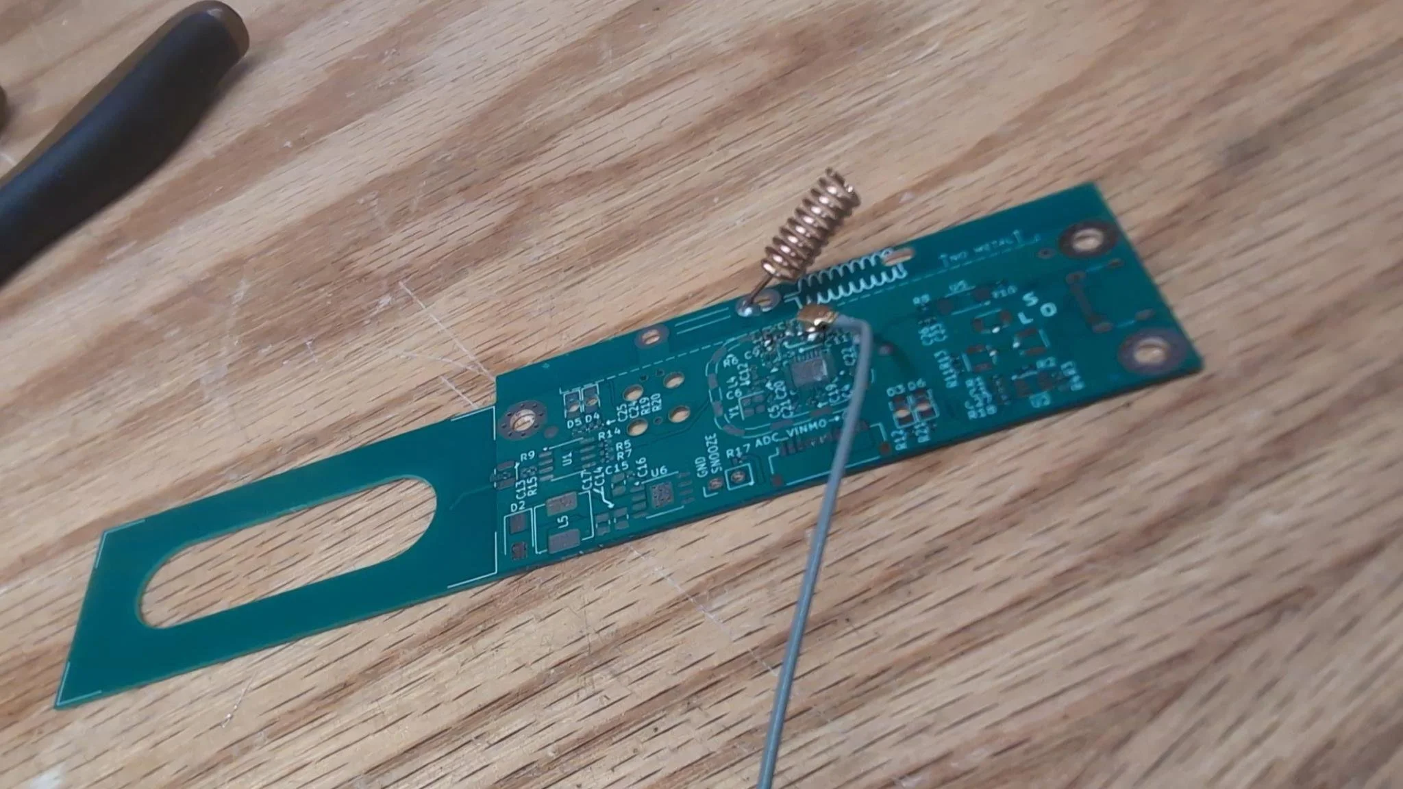
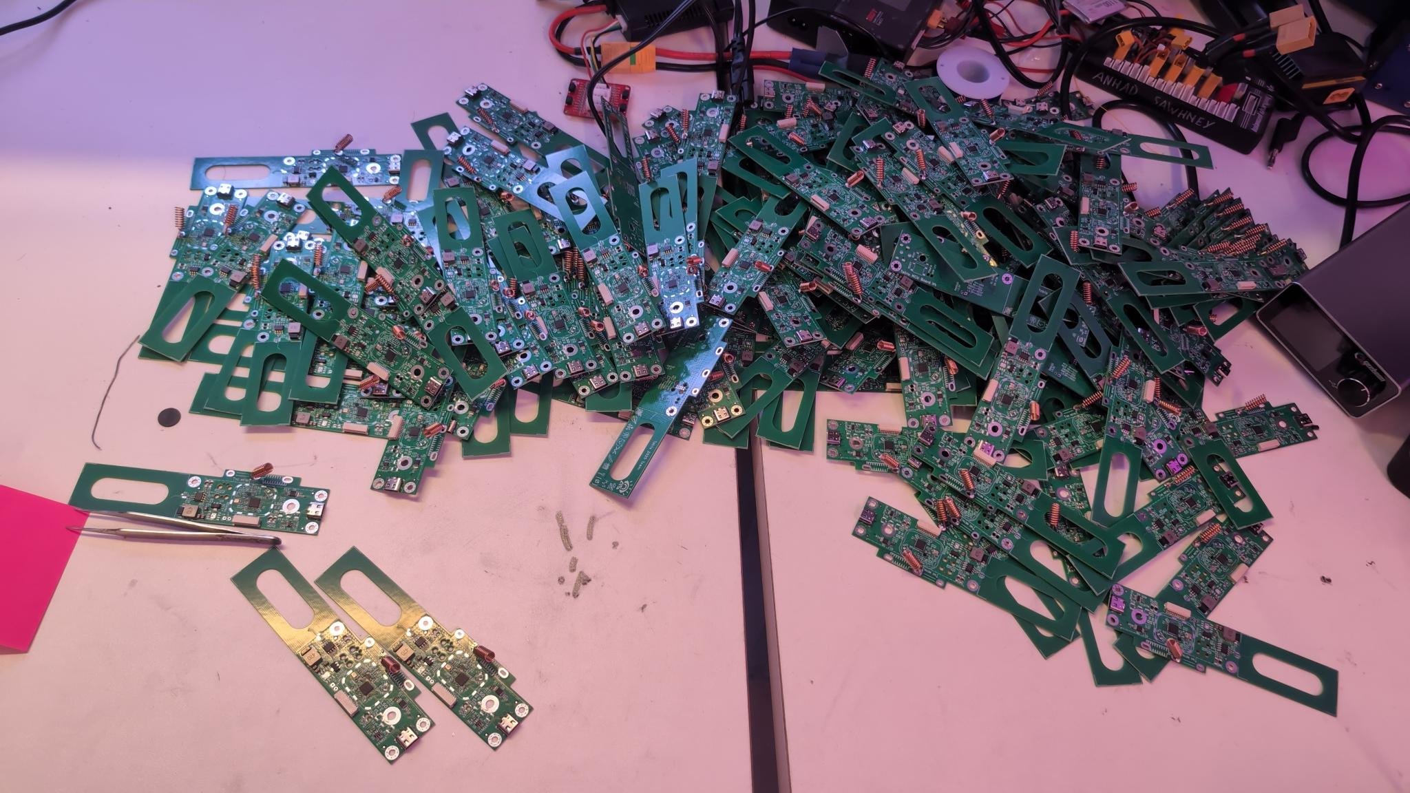
Luckily, I had left a footprint for a linear regulator on the production board just in case there was an issue with the buck converter. Once the boards came in, we sat down and removed all the buck converters and added linear regulators in their place.
During this time, I also discovered that orienting the antenna diagonally enhanced its performance by moving it farther from the aluminum enclosure, so we made a 3D printed jig and hand soldered all of the antennas on the boards at an angle.
Thermal characterization pre CPW (April 2026):
With the production hardware in hand, I also set about calibrating the NTC thermistors on the LED board so that the MCU could accurately measure the temperatures of the LEDs and compensate for it. The NTC displayed some extremely strange behavior where the measured voltage would change in a nonlinear manner as the power commanded to the LEDs changed. There were a number of odd influences to the NTC behavior so I ended up measuring a few curves at different LED power levels and fitting a model to them to back out the actual temperature.
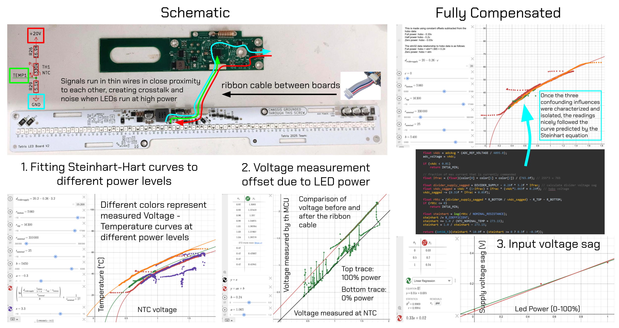
Alongside this I also measured how the temperature of the enclosure related to the temperature of the LED board, and we created a basic thermal model of the enclosure temperature to implement in firmware. We implemented thermal throttling to control for both the temperature of the enclosure (so occupants of the Green Building could not burn themselves by touching it even if we were running a static display with some lights on all night) and the temperature of the LEDs (to avoid burning them out).
Mass production part 1 (April 2026):
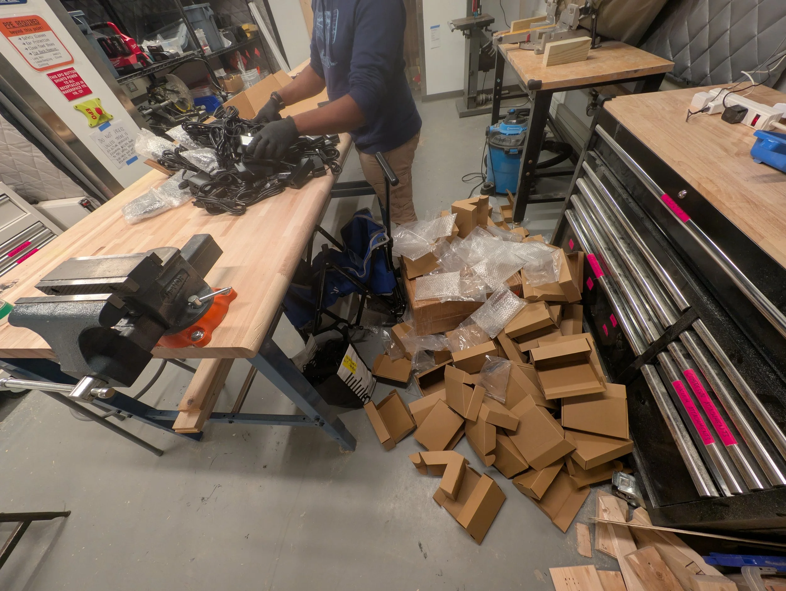
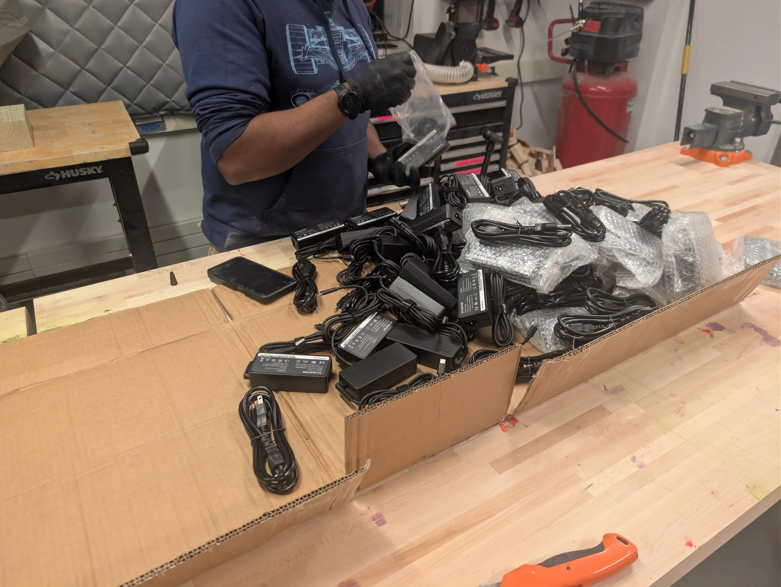
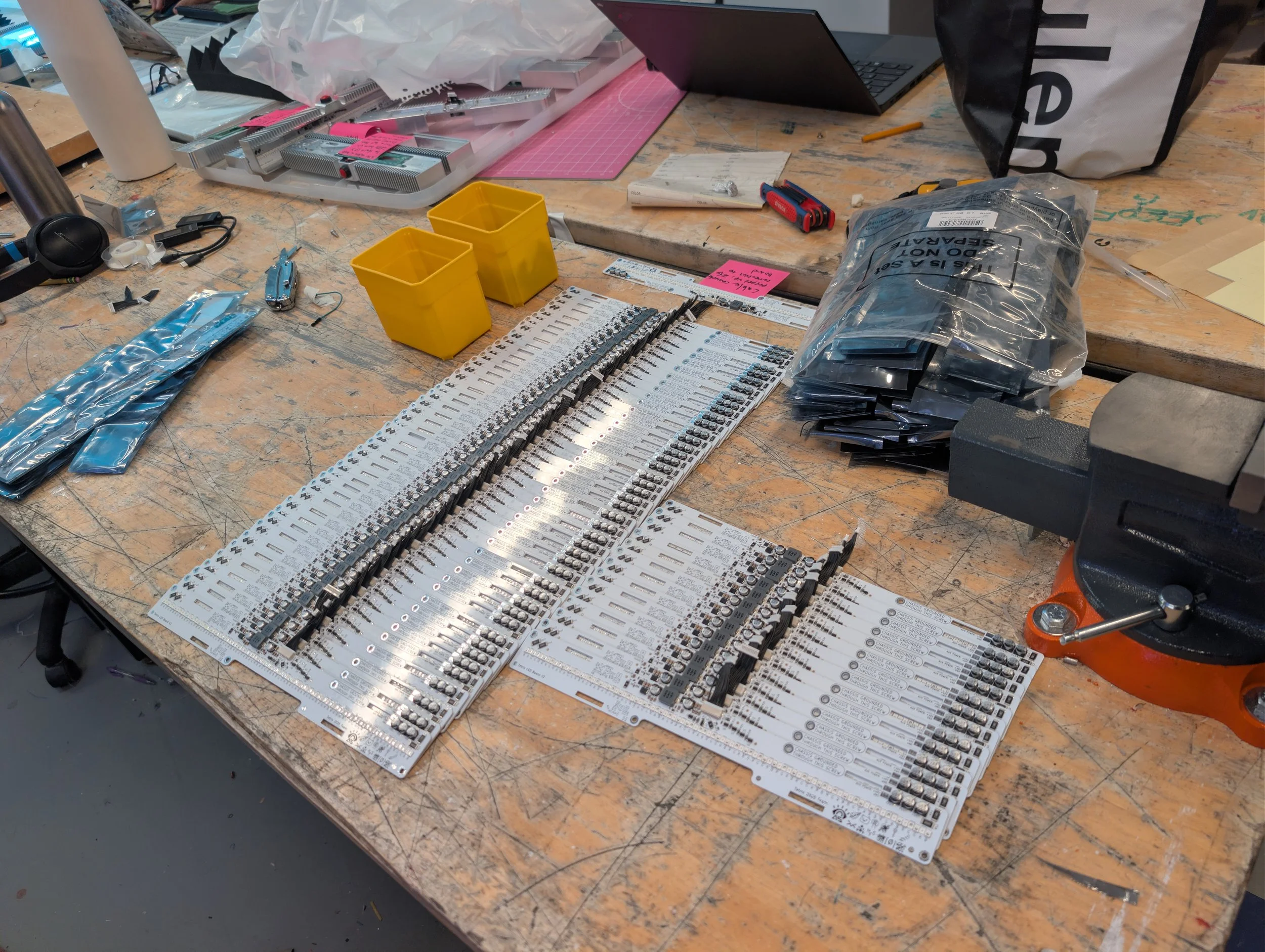
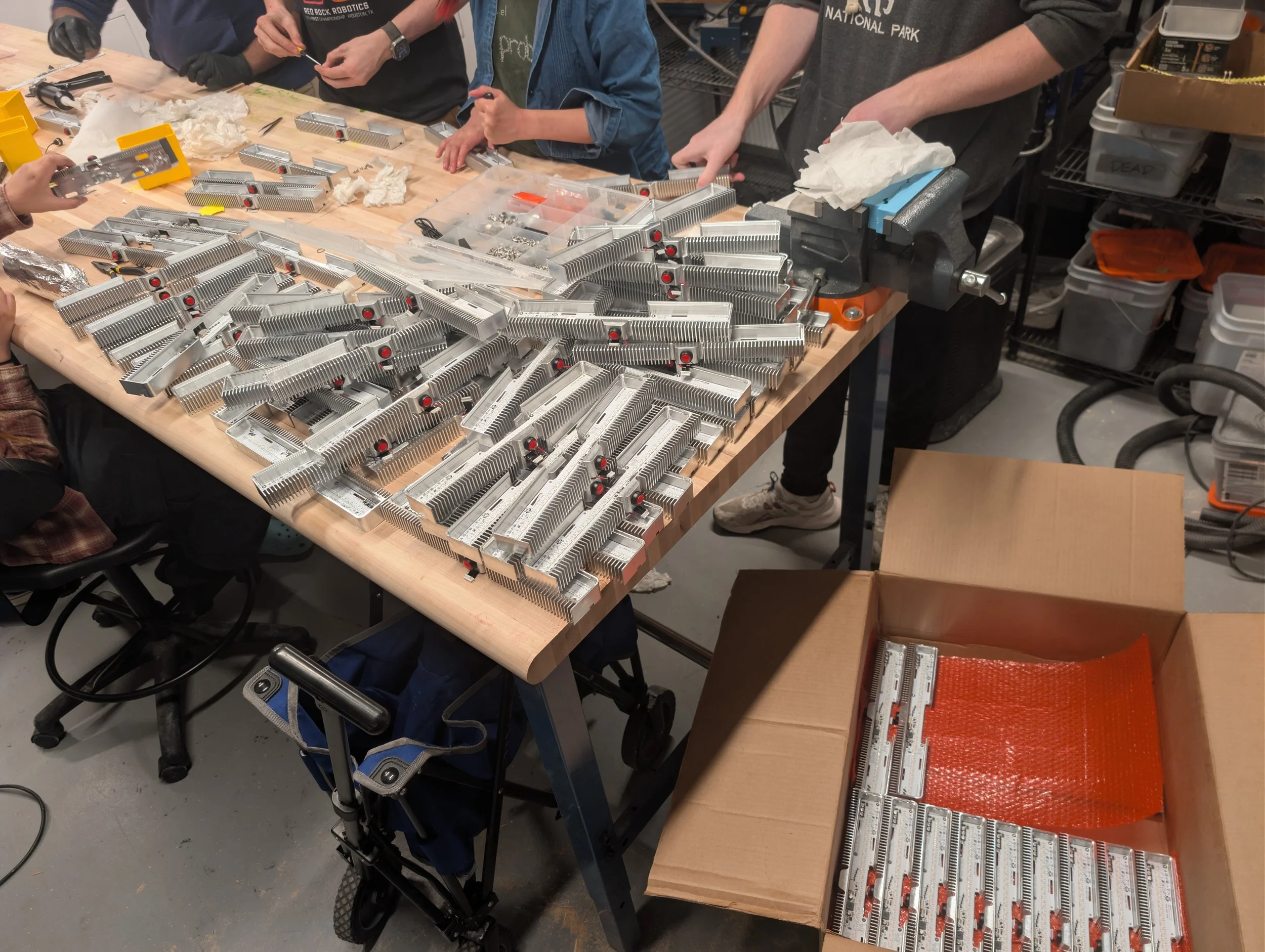
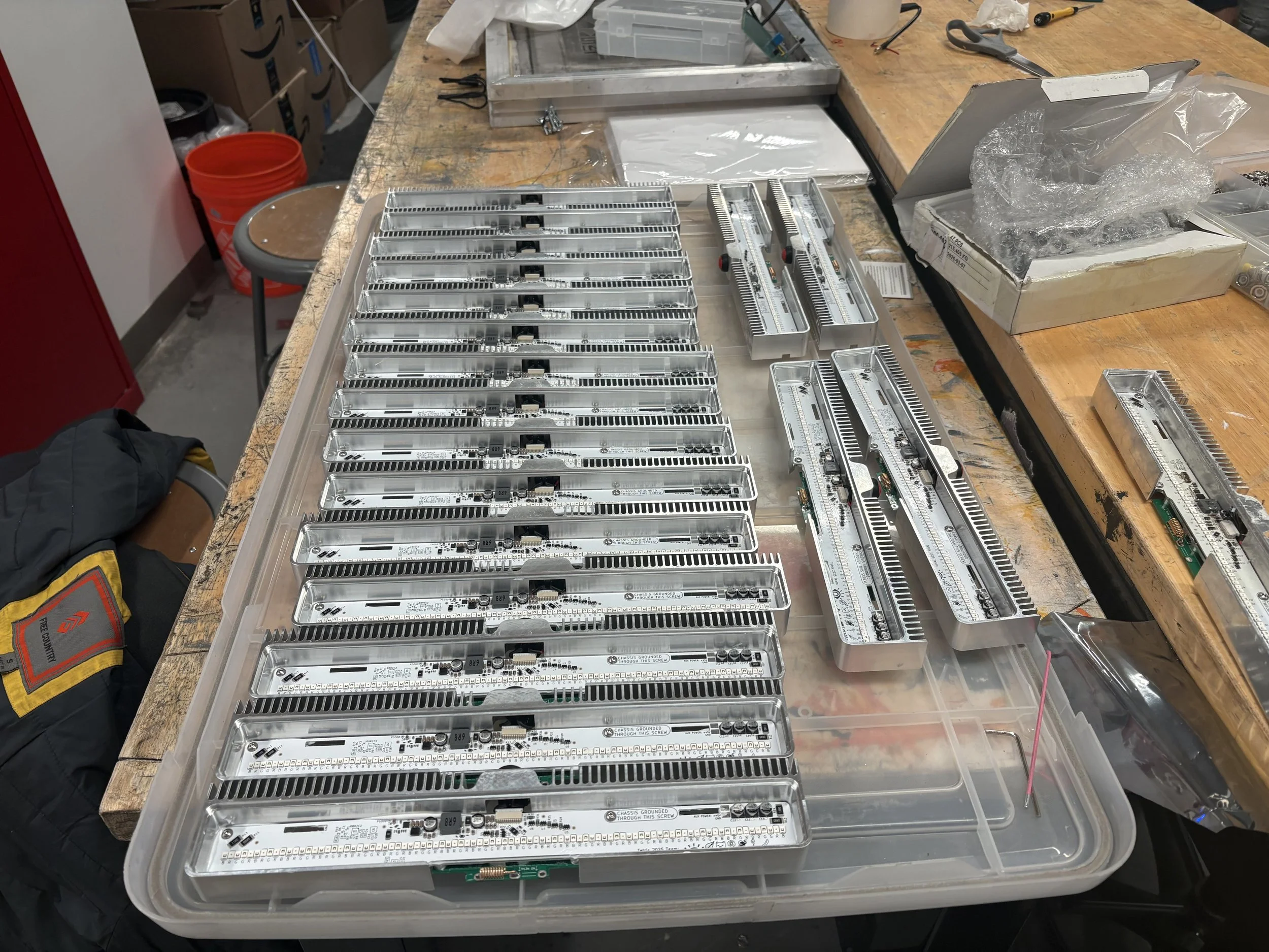
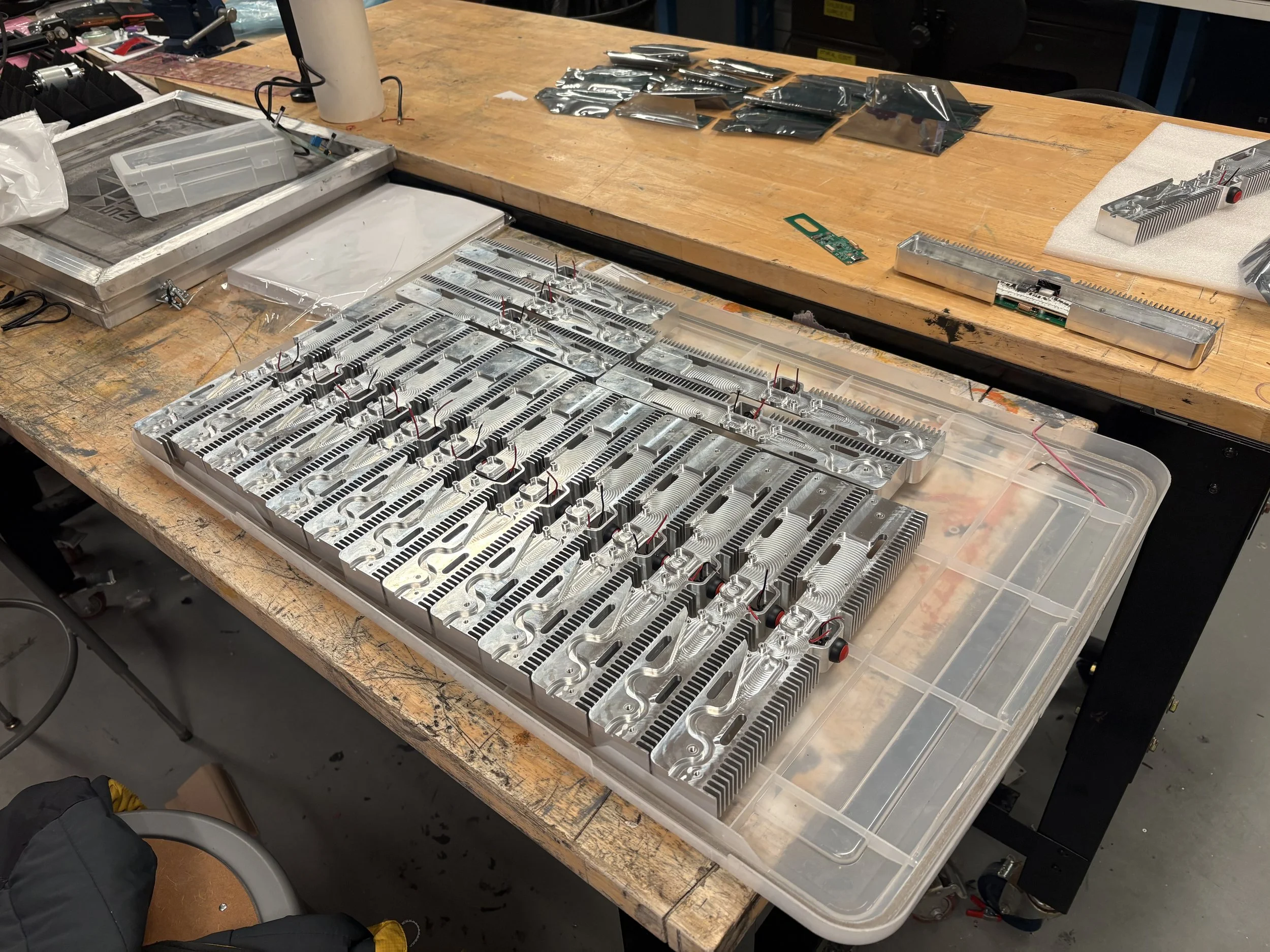
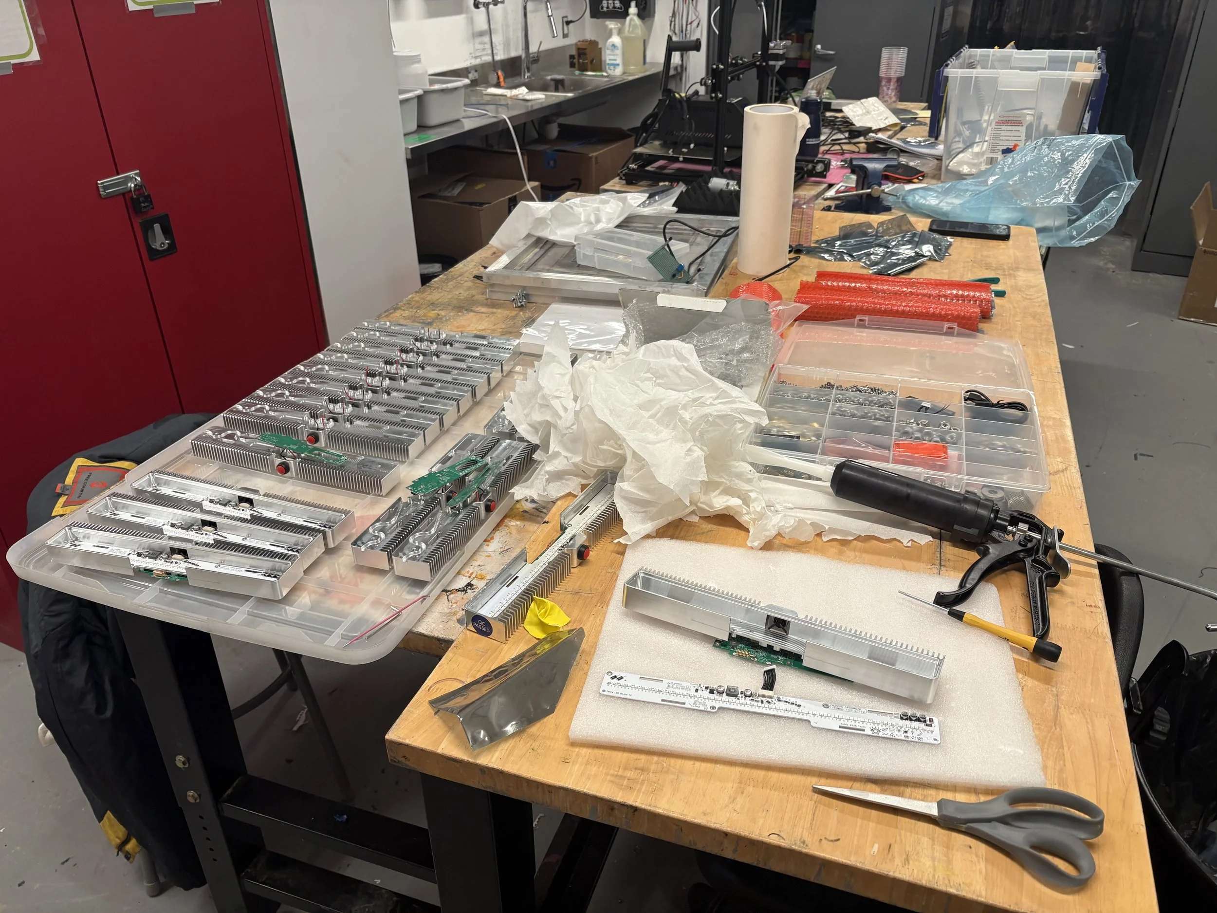
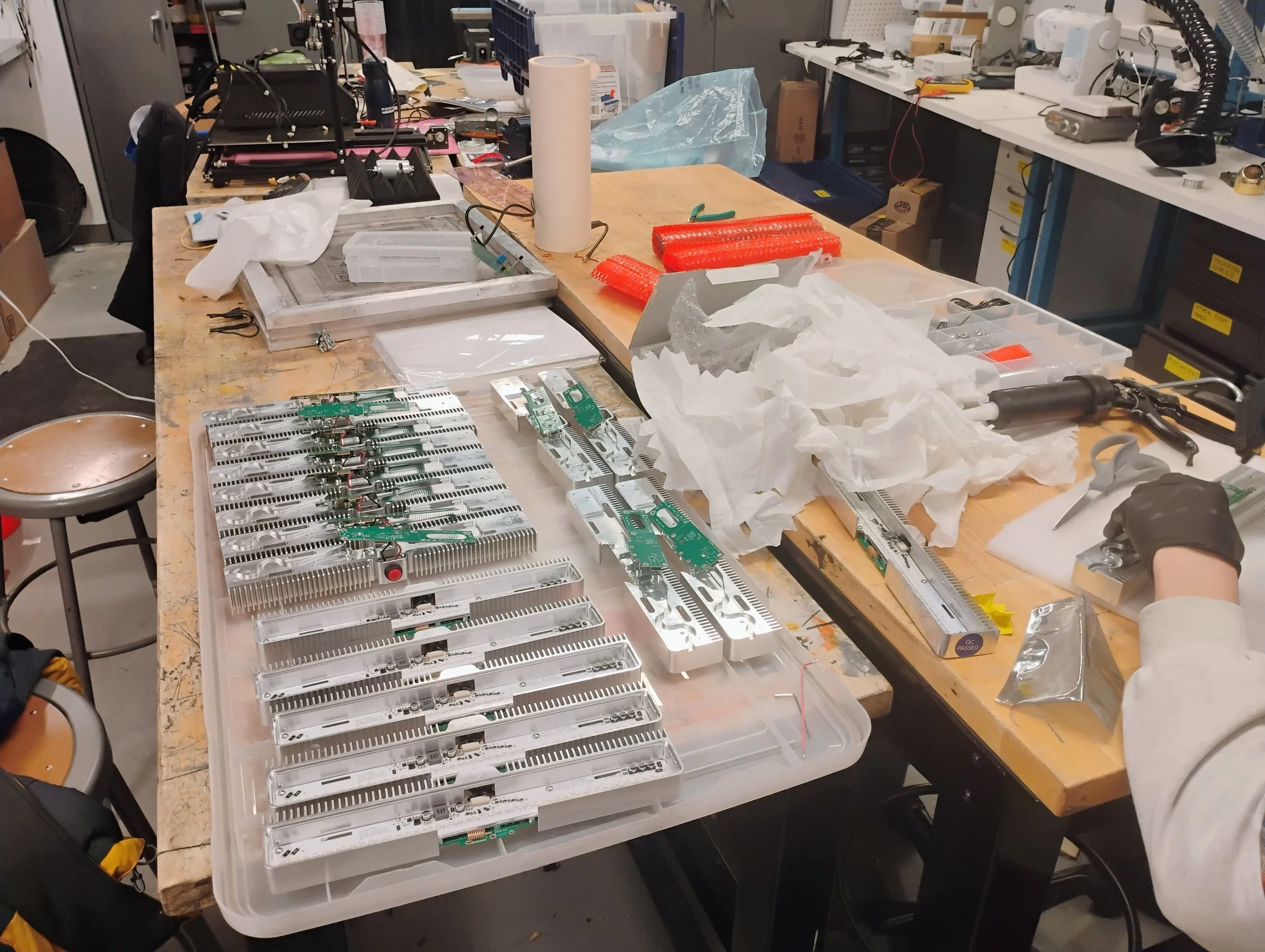
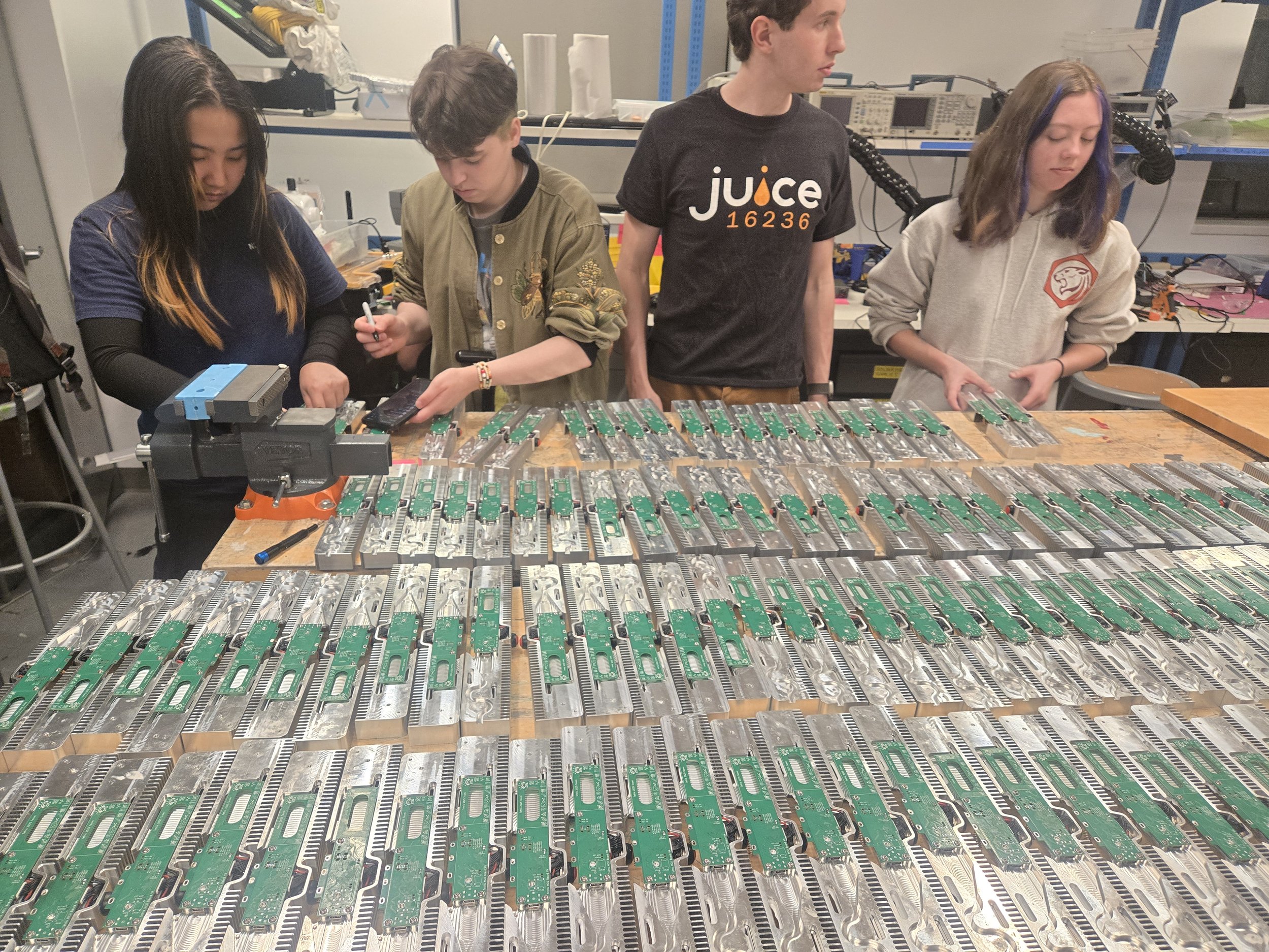
All of our orders from China came in over spring break. When we returned from spring break we had just two short weeks to assemble all 153 modules (+ spares) and deploy them into all the rooms in the Green Building. (Not to mention this was amidst all the classwork, exams and other preparations that happen for CPW).
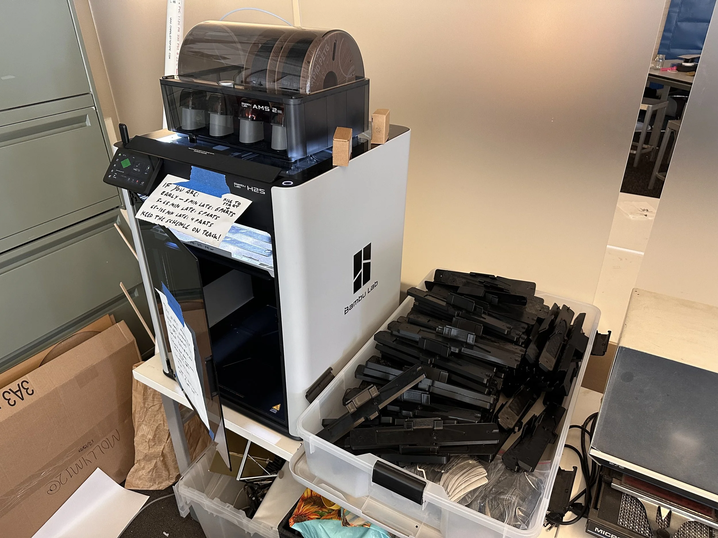
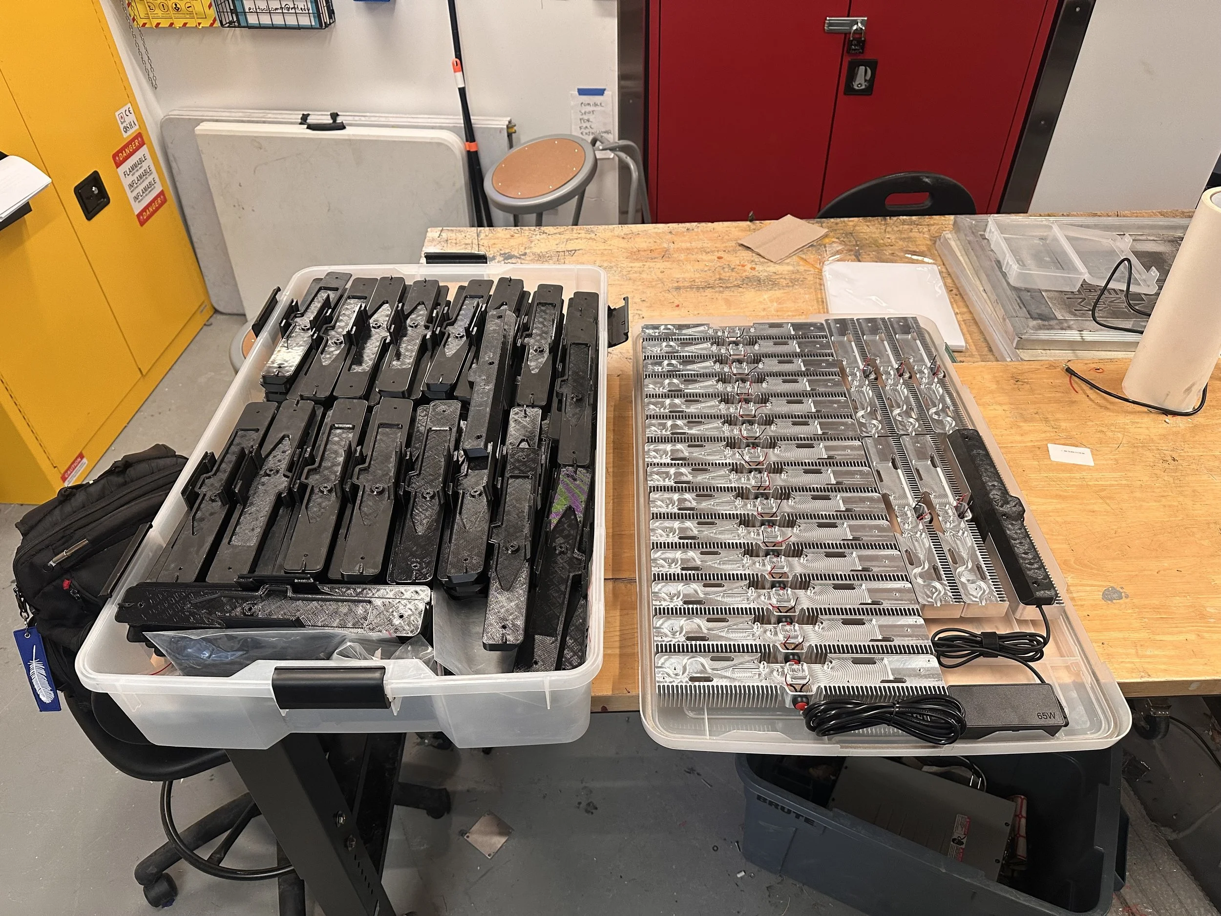
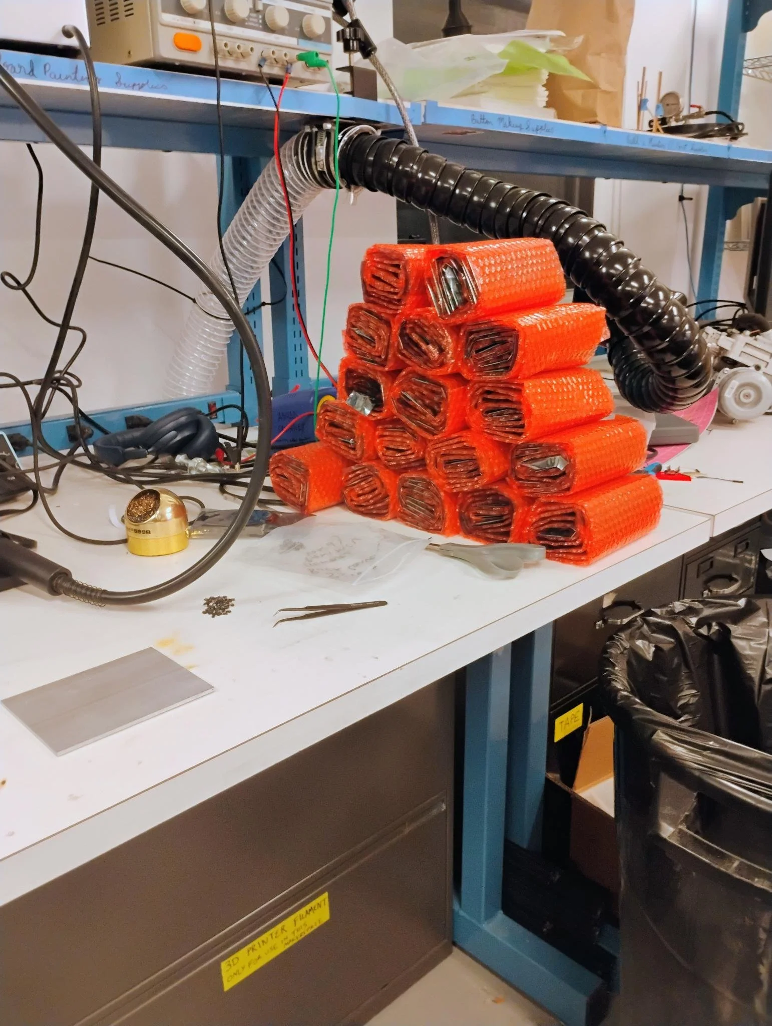
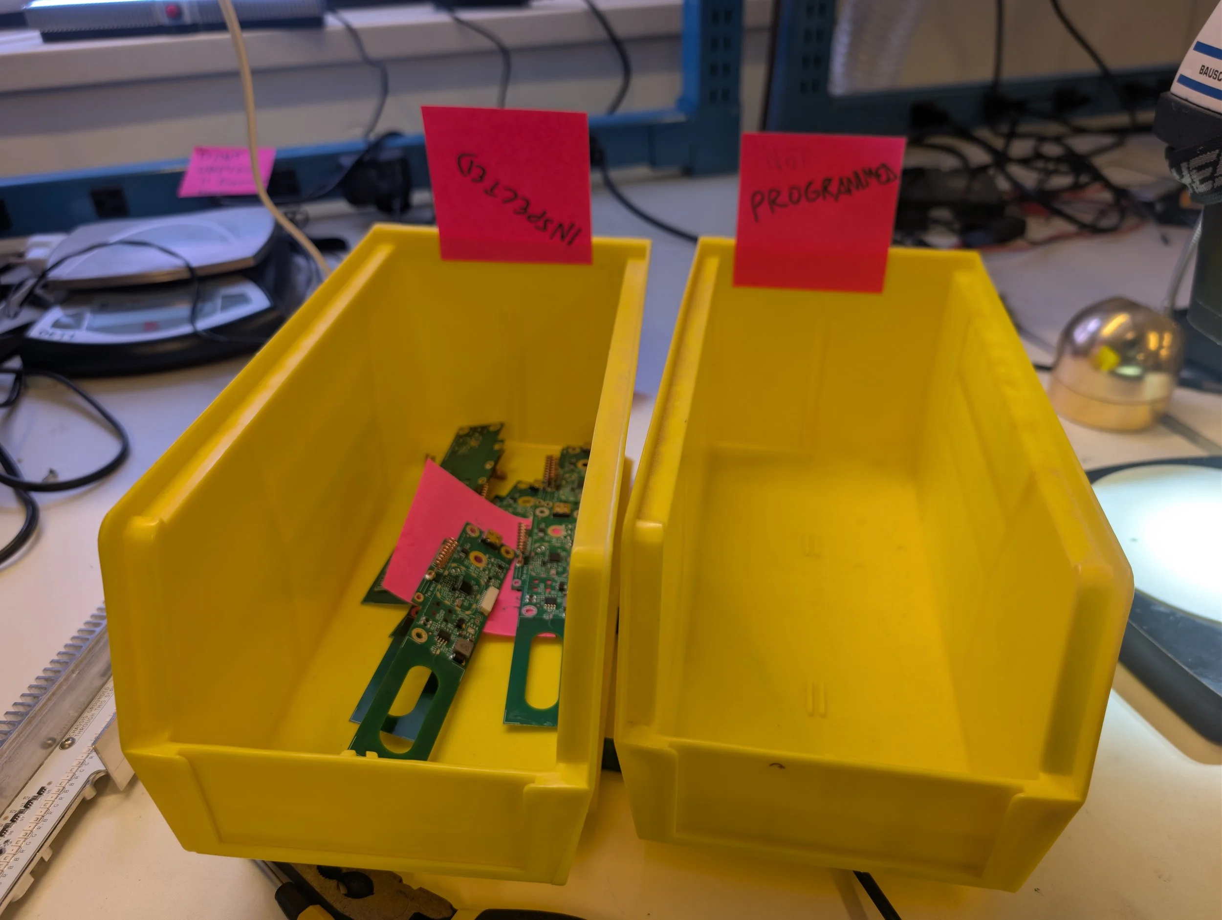
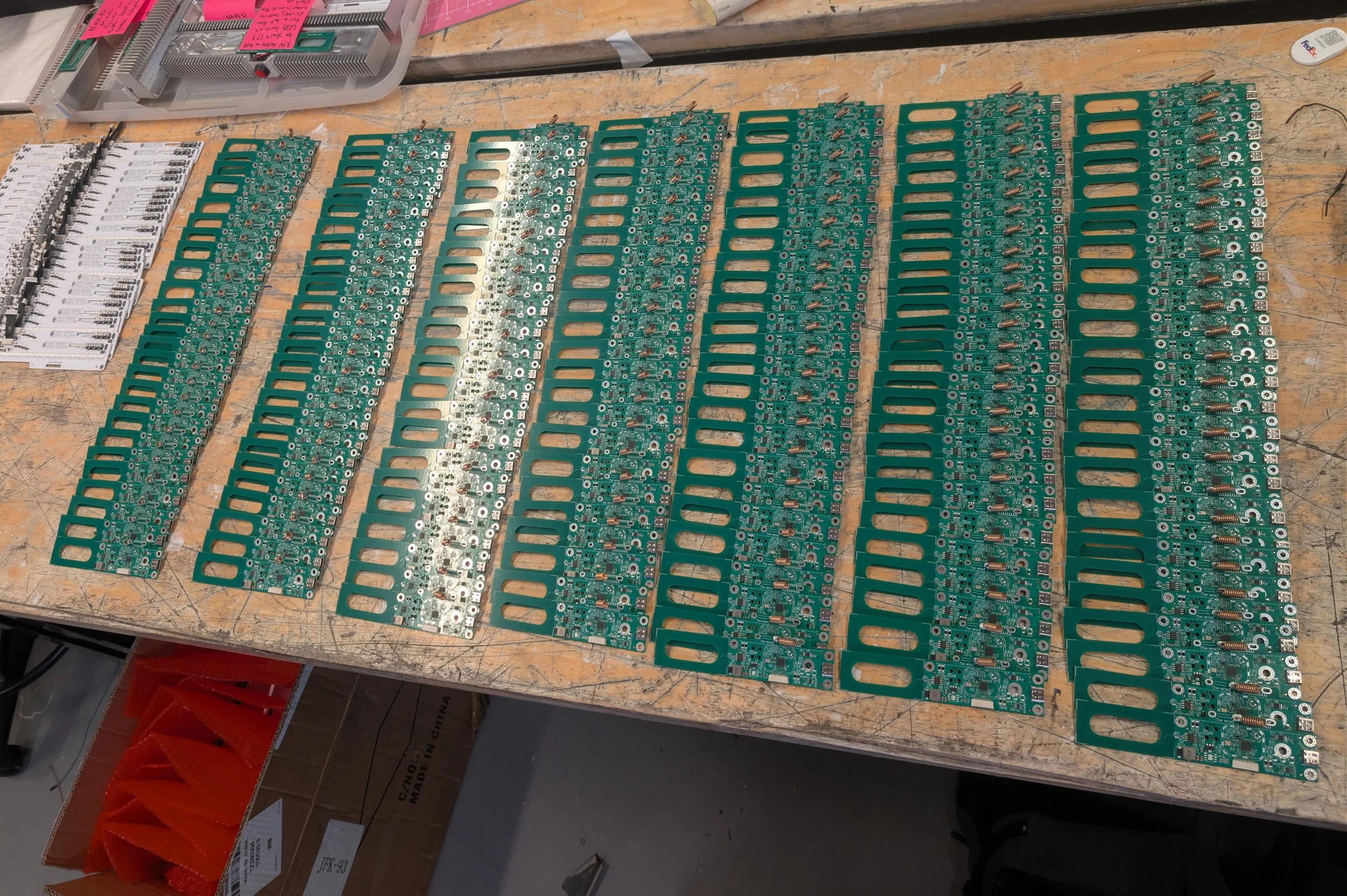
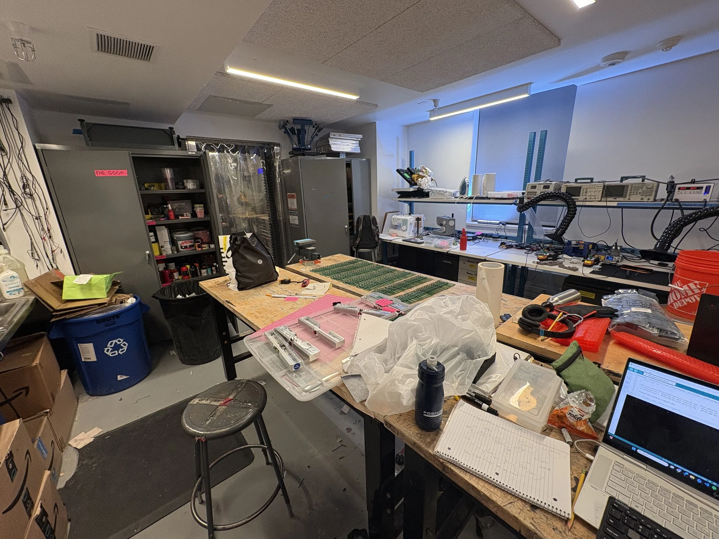
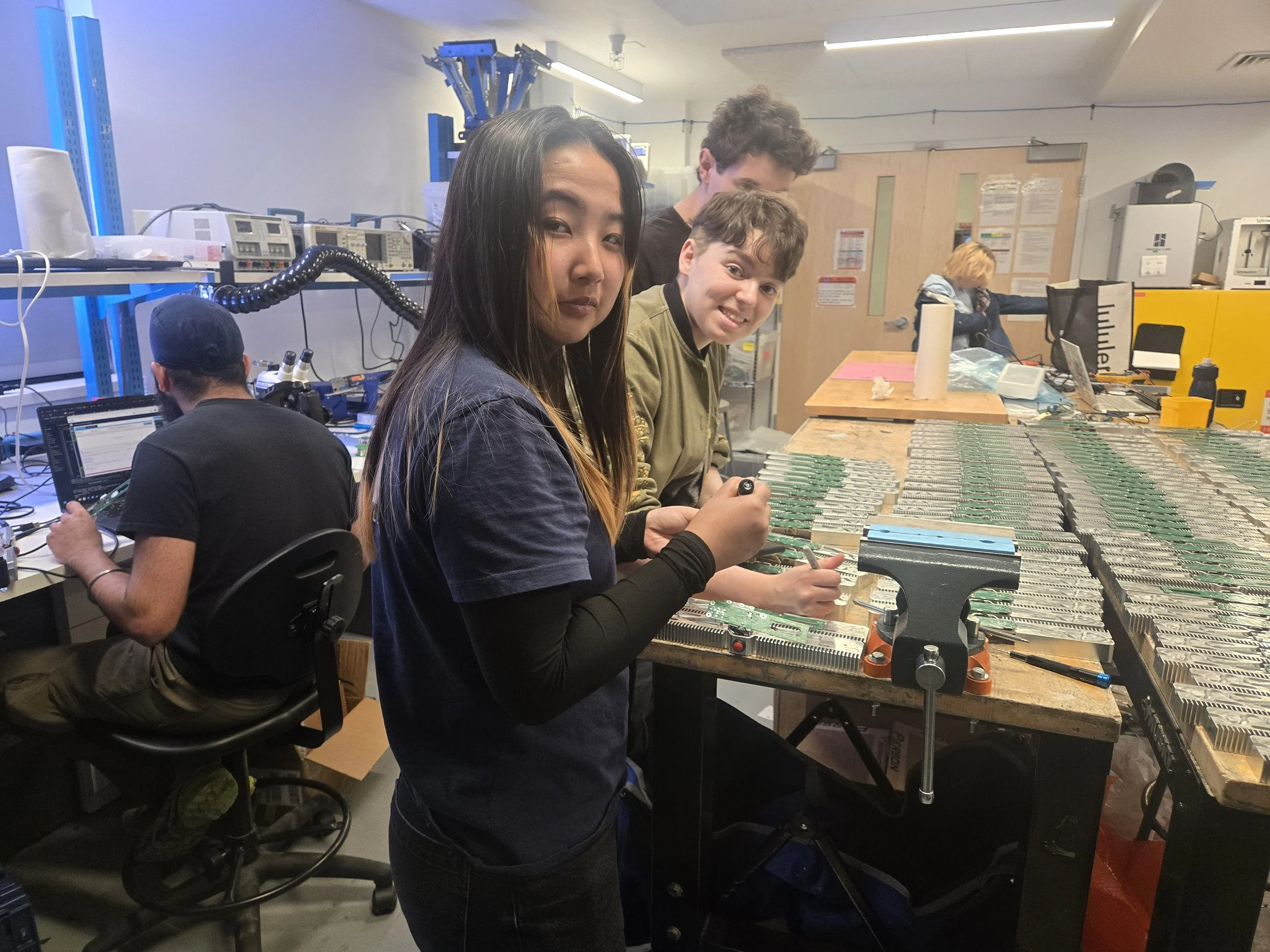
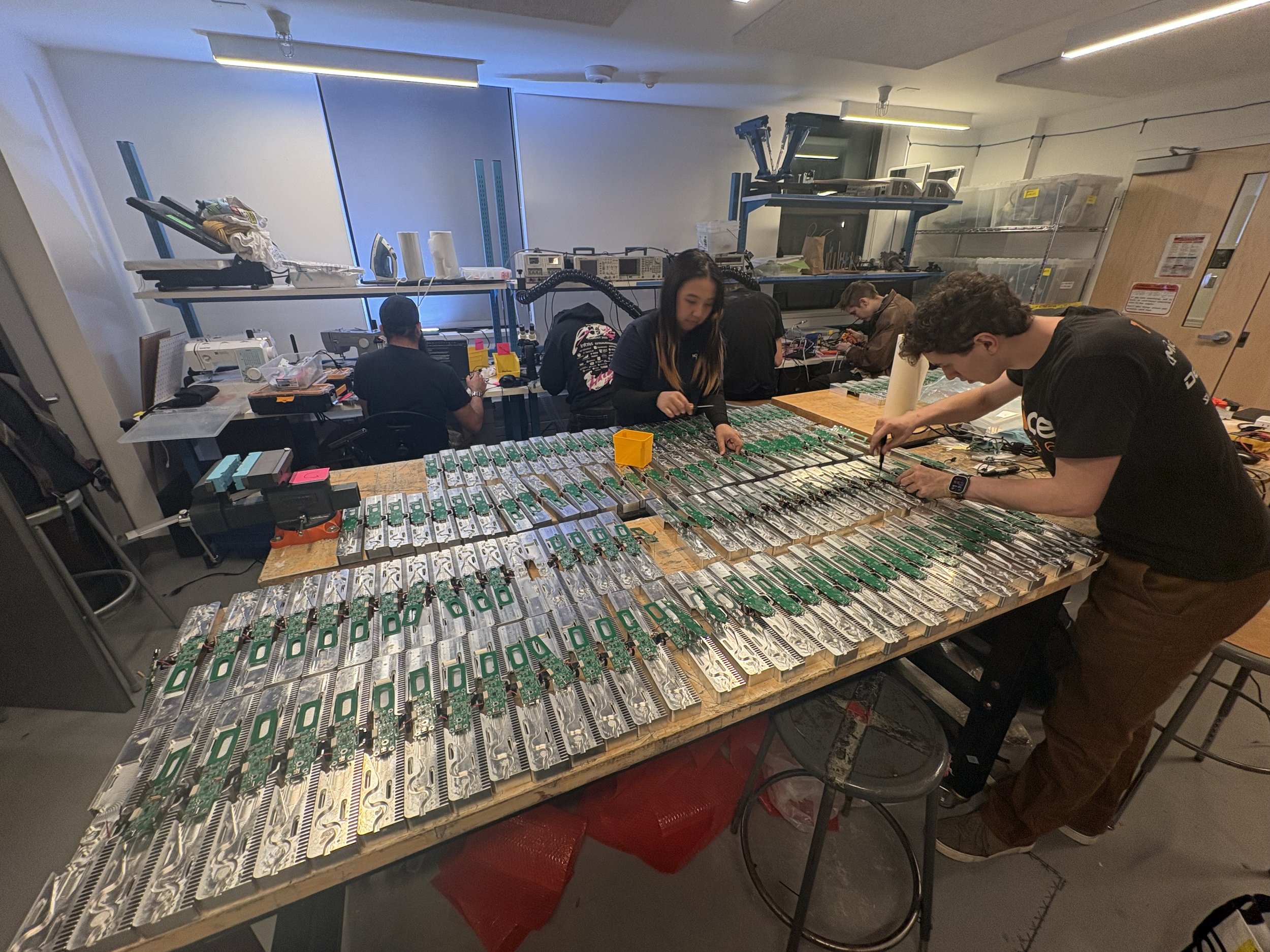
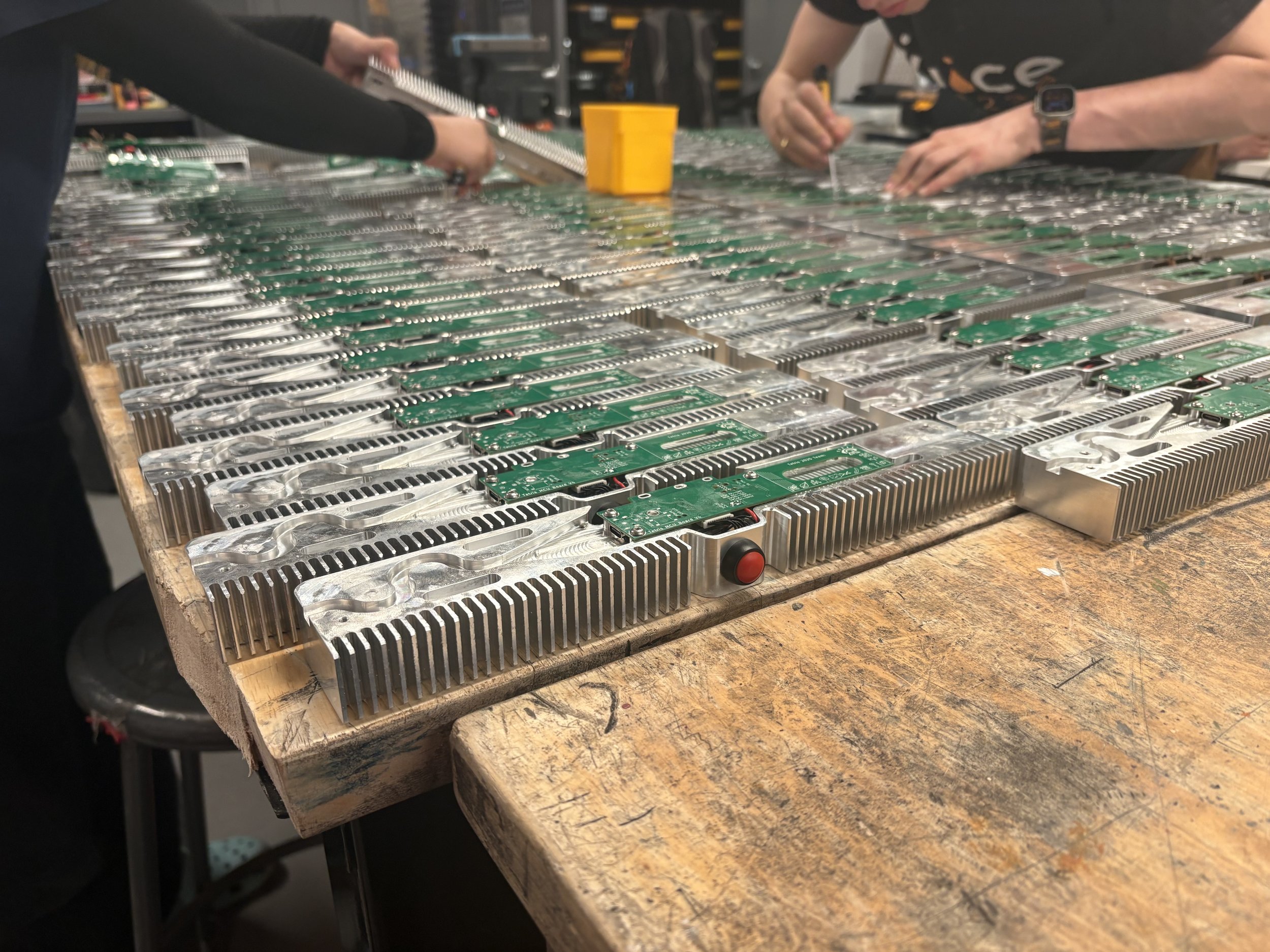
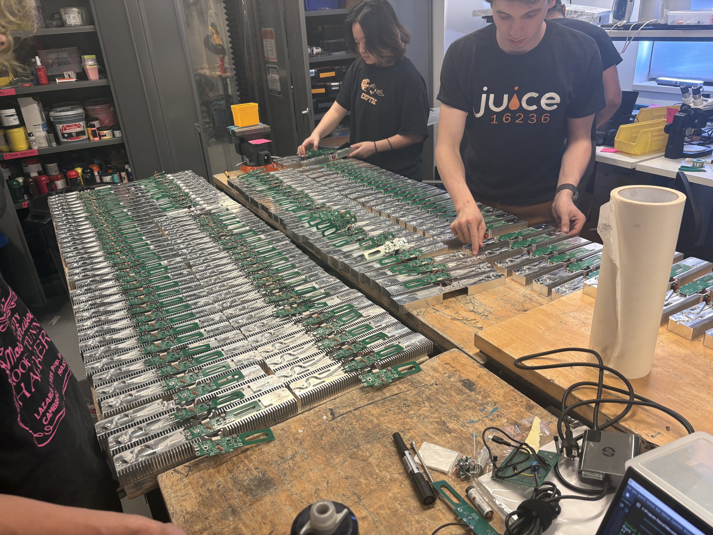
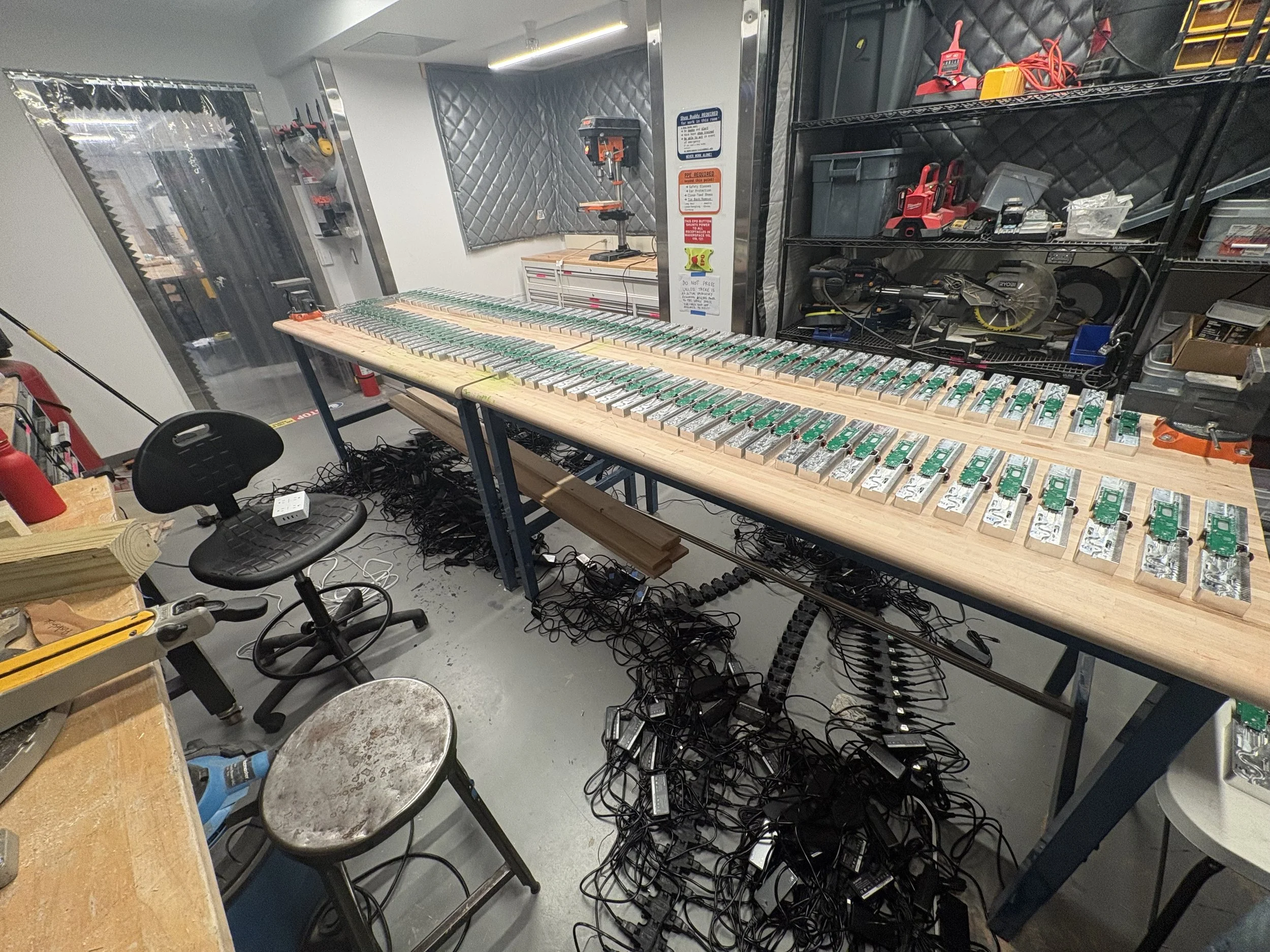
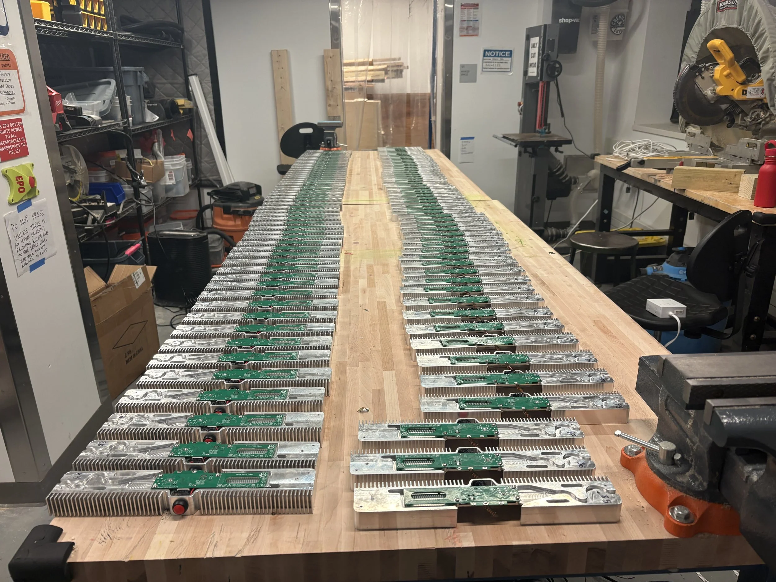
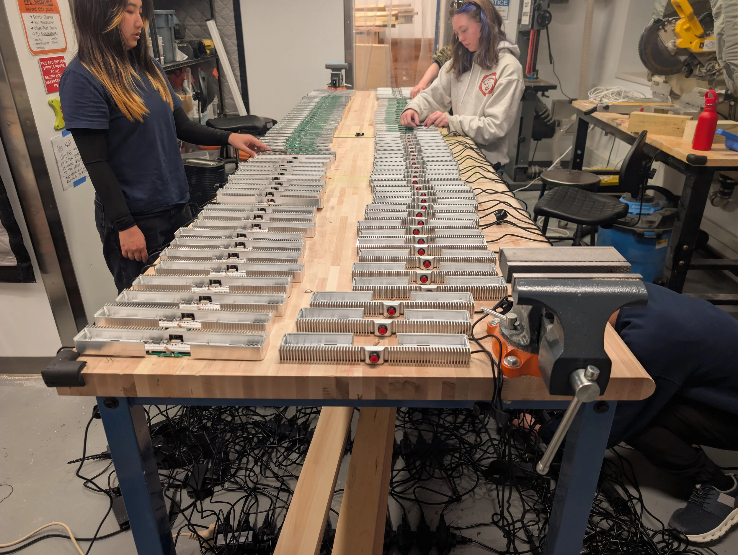
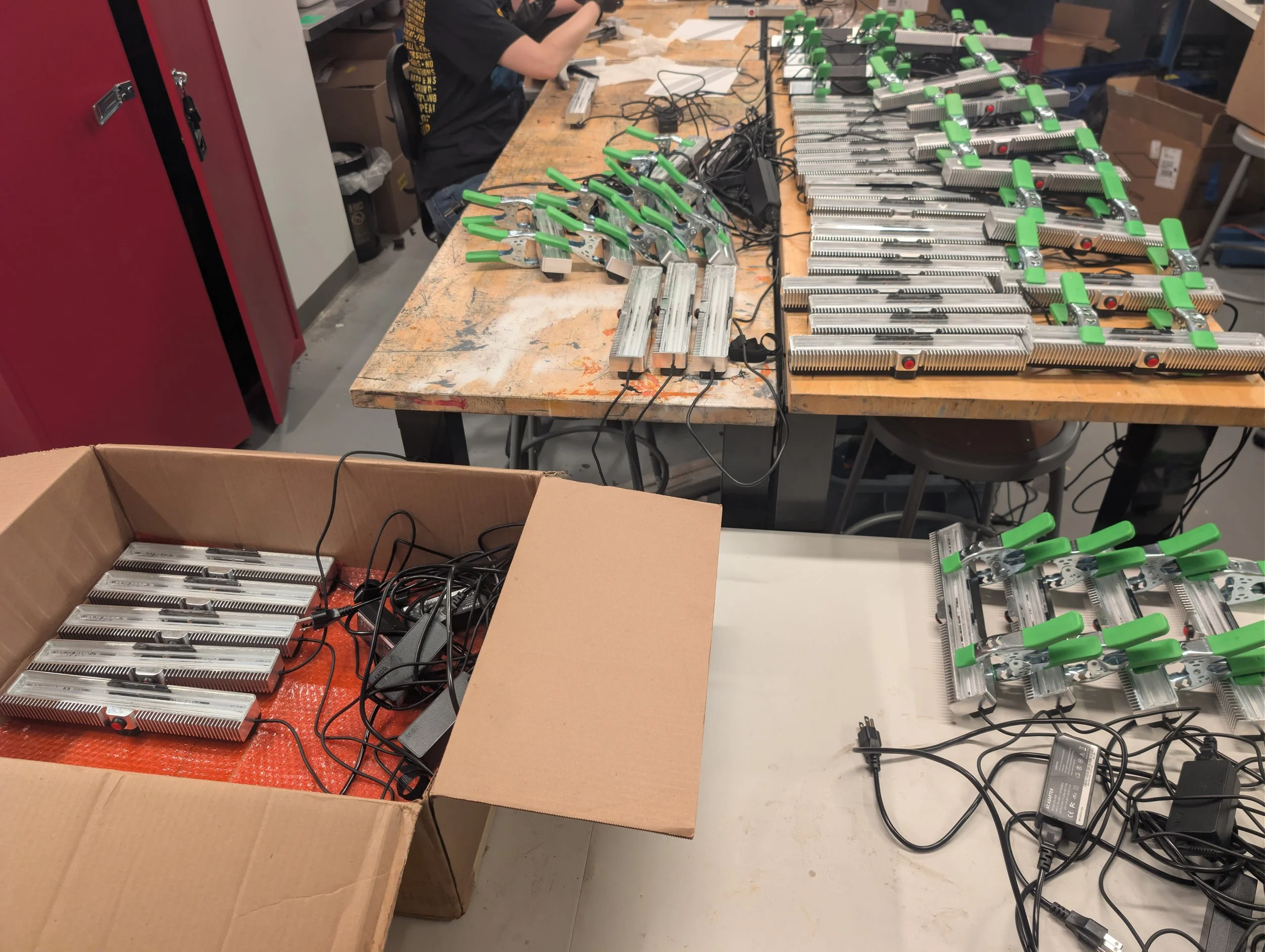
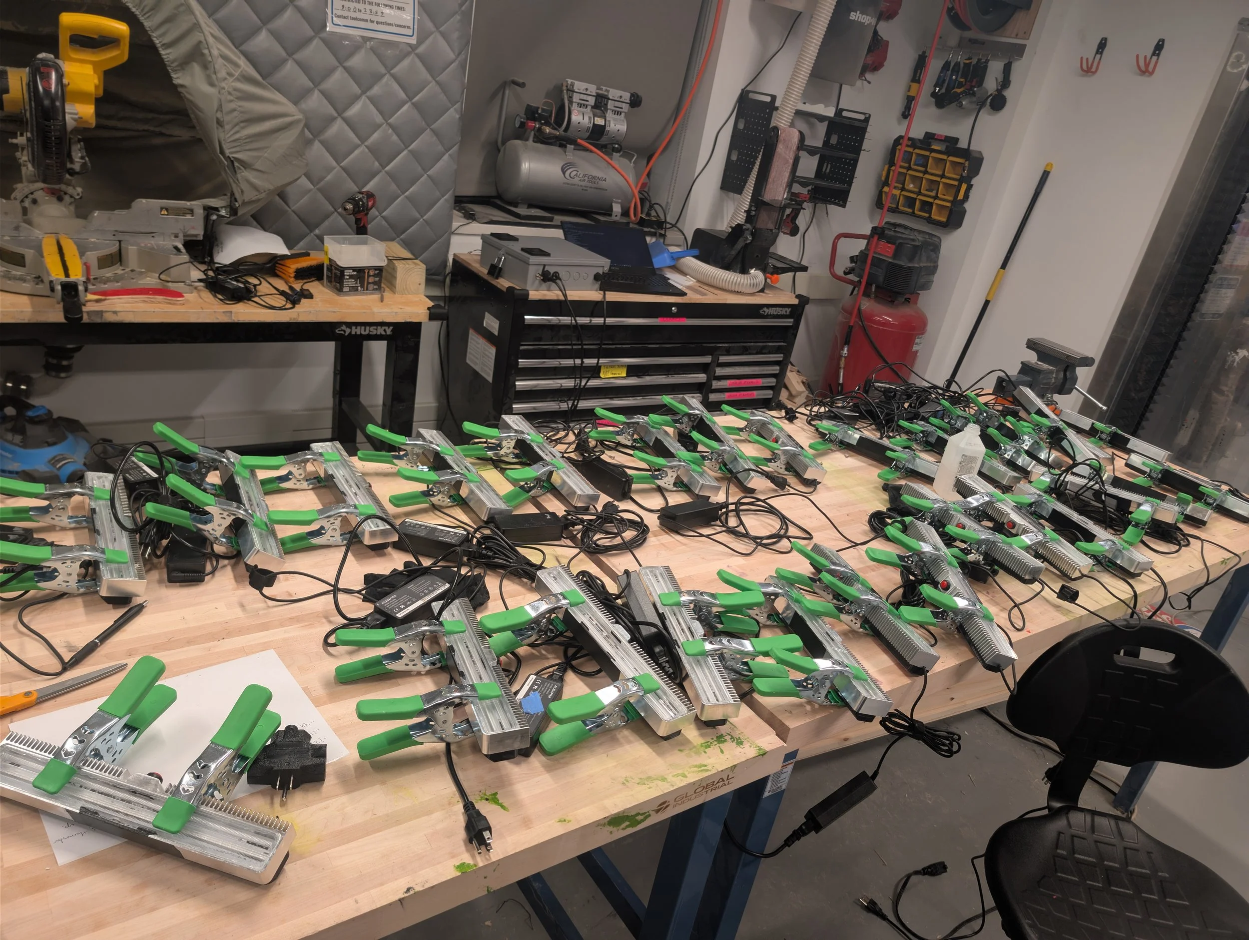
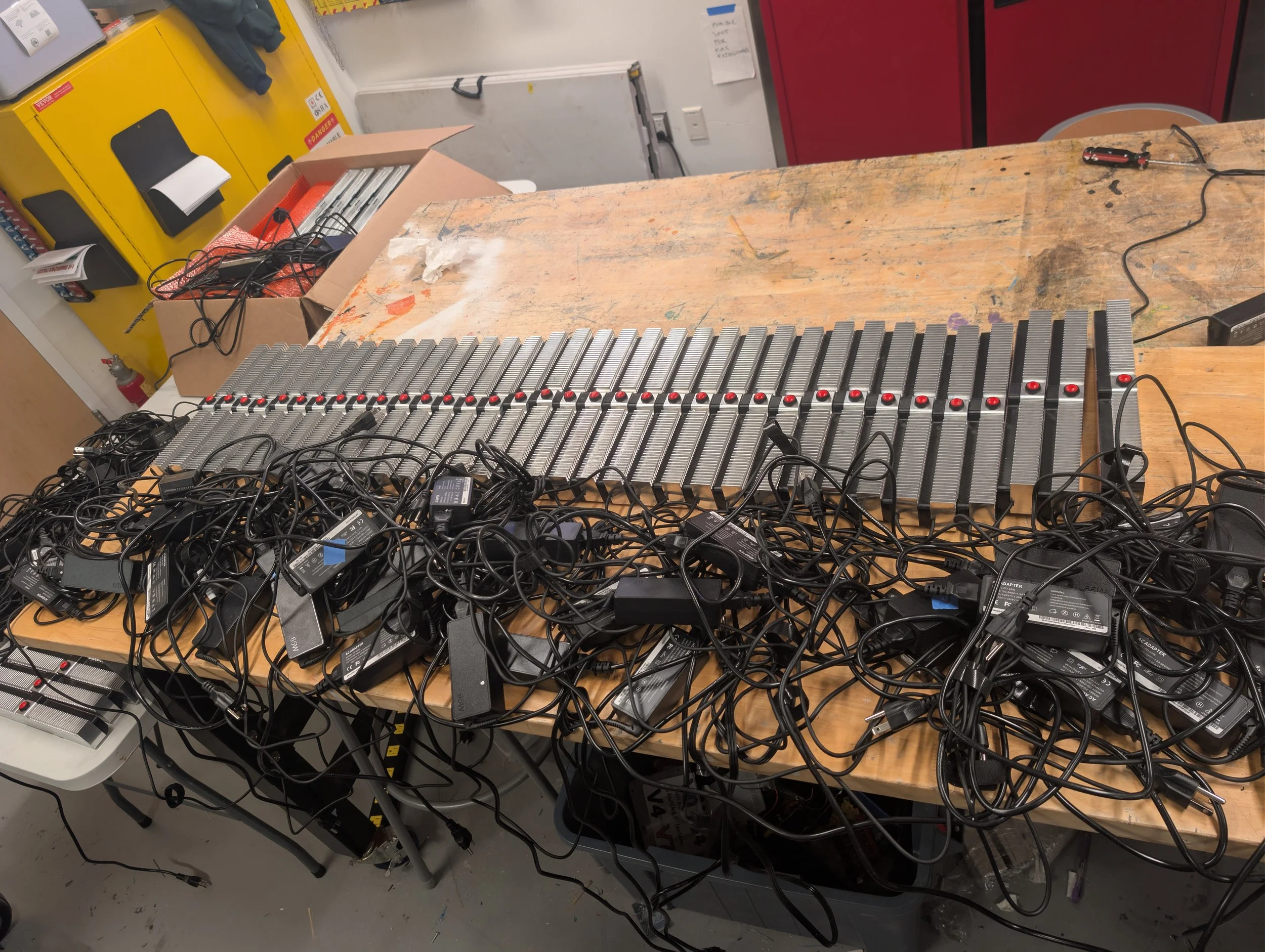
In order to tackle this herculean task, I basically did not attend class for the entire week, and recruited over 50 people through emails and sign up sheets to contribute what little time they had to the assembly line. I made sure I was constantly available throughout every day so that we could make use of every minute and there would be no times when people would not know what to do. We set up our production line in the EC makerspace and began cranking out modules.
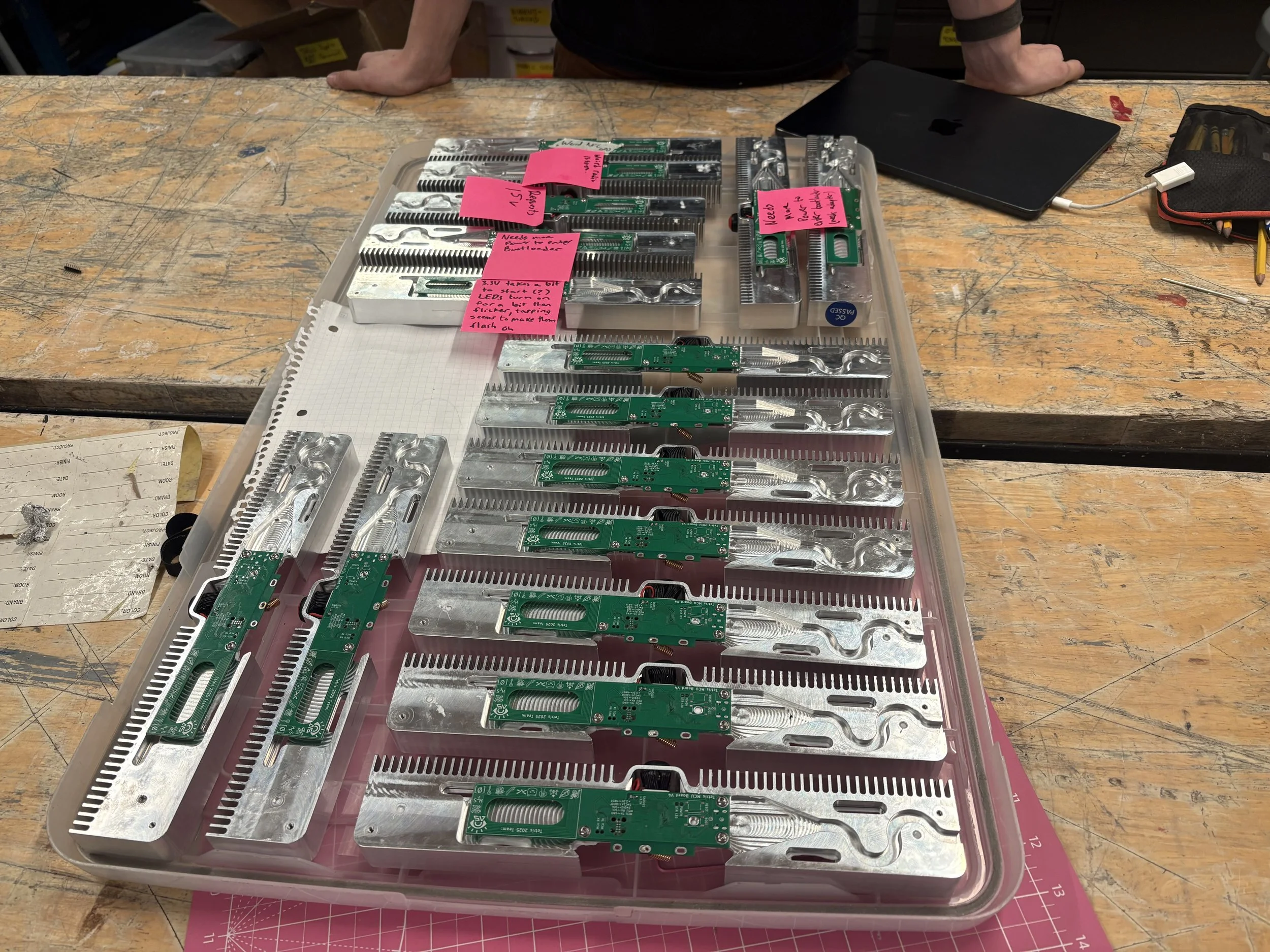
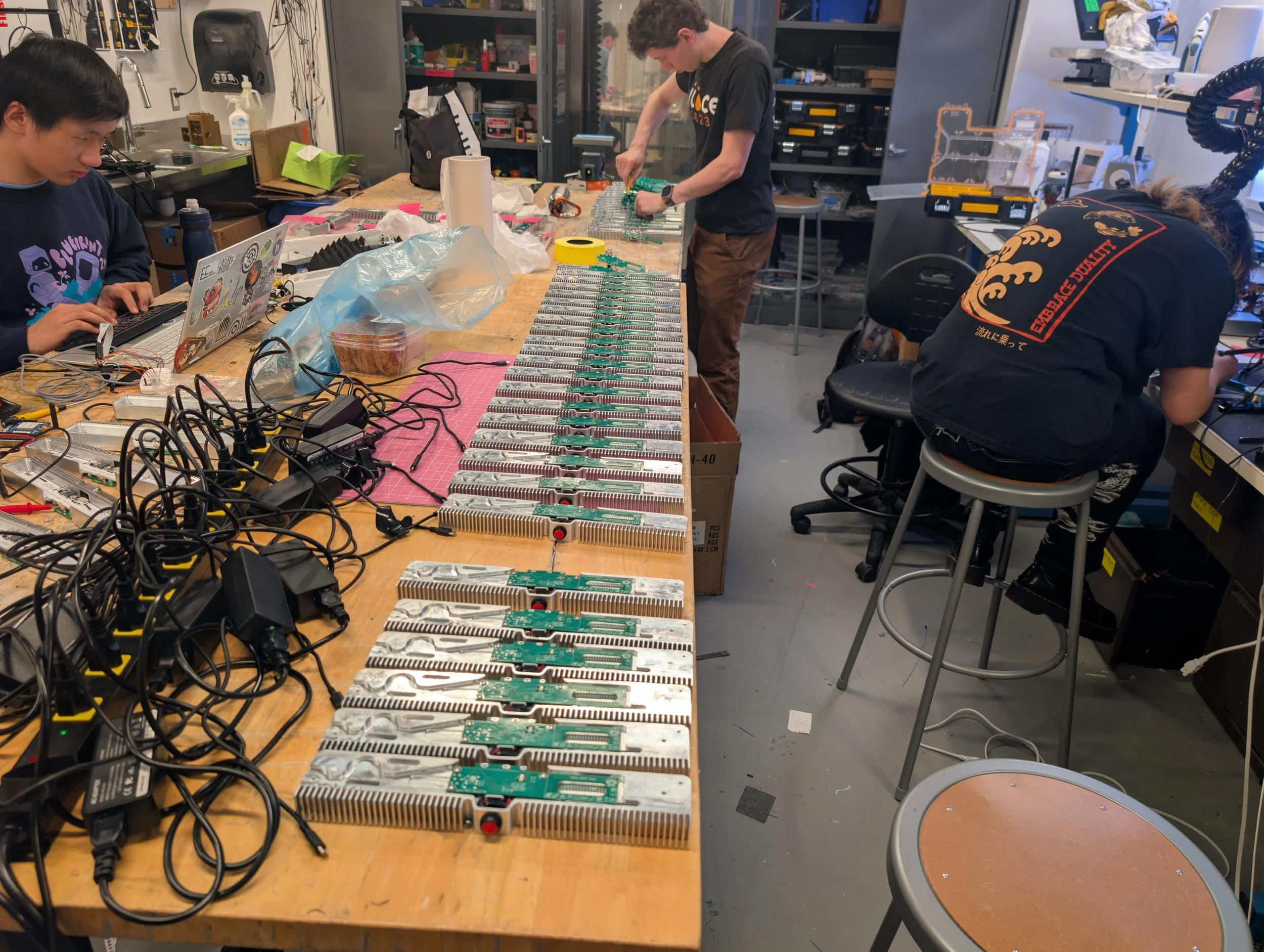
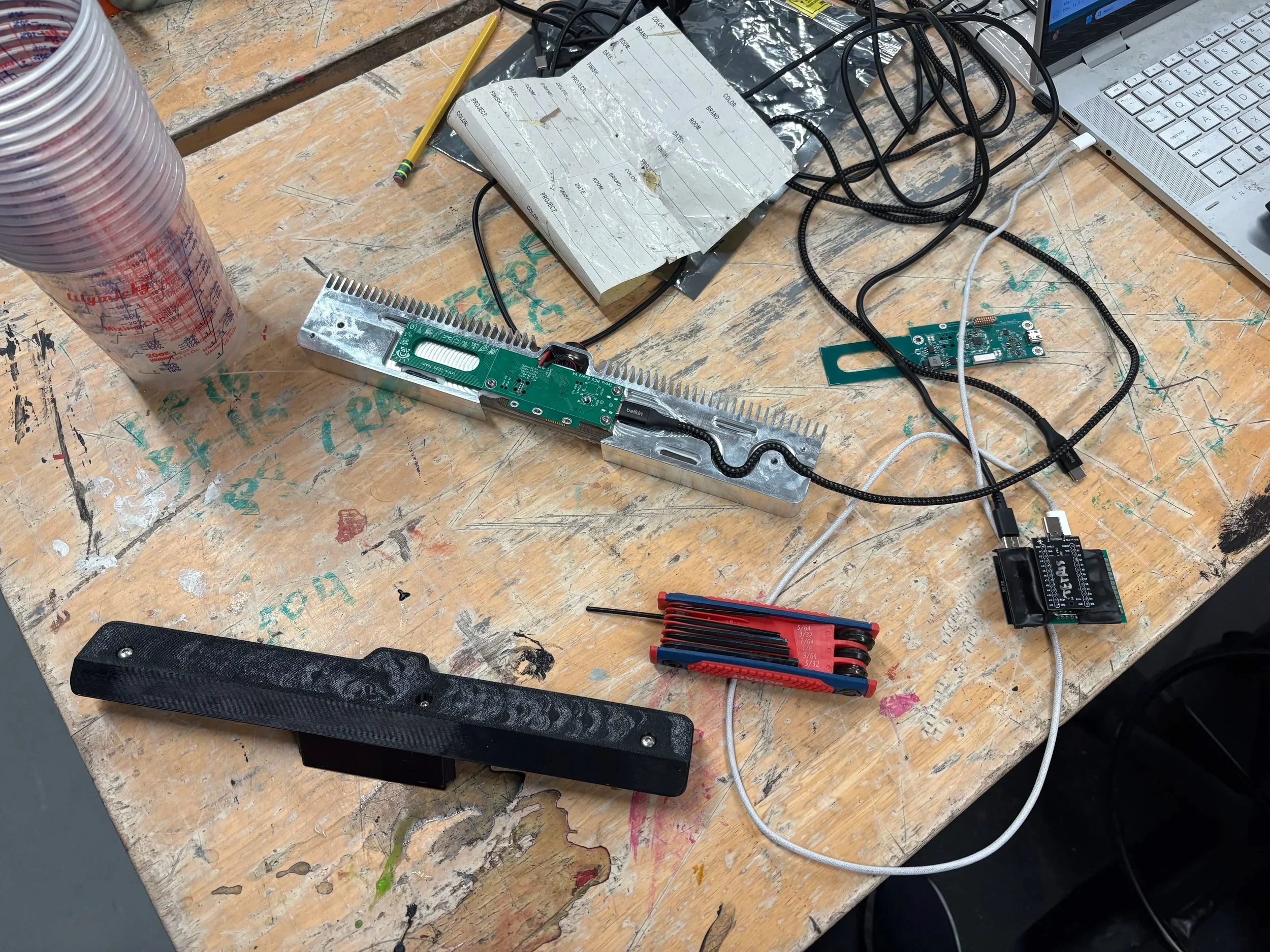
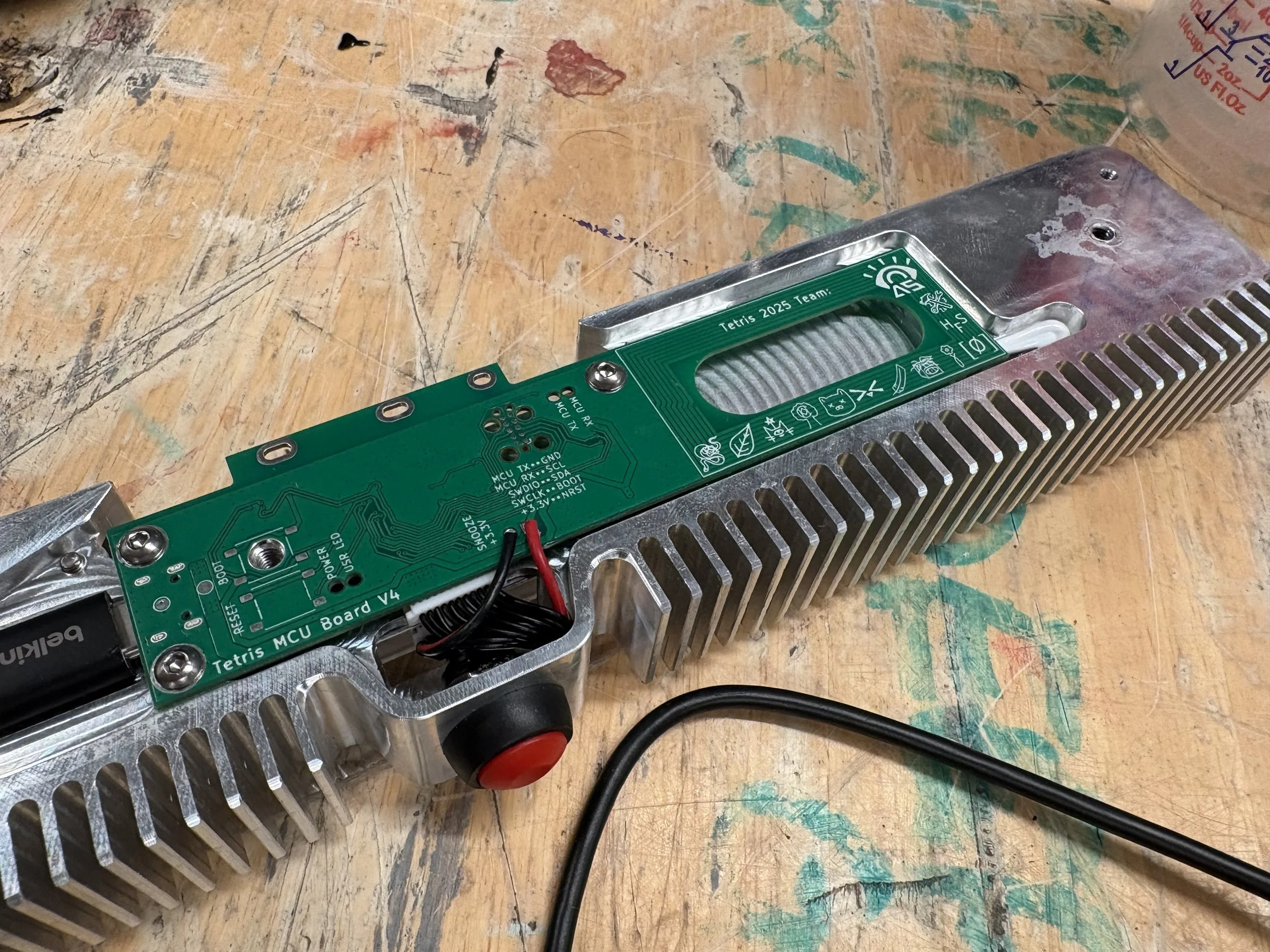
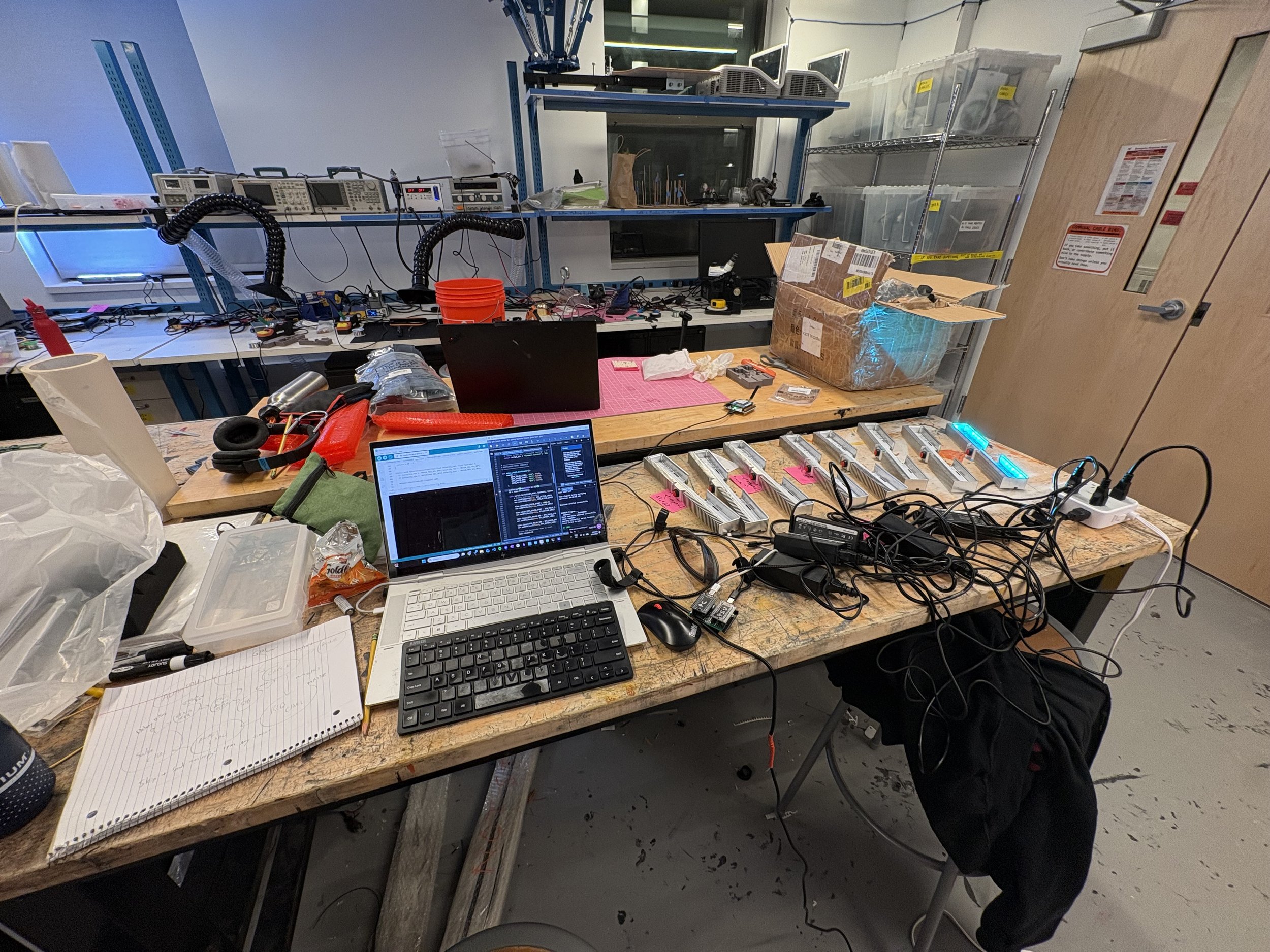
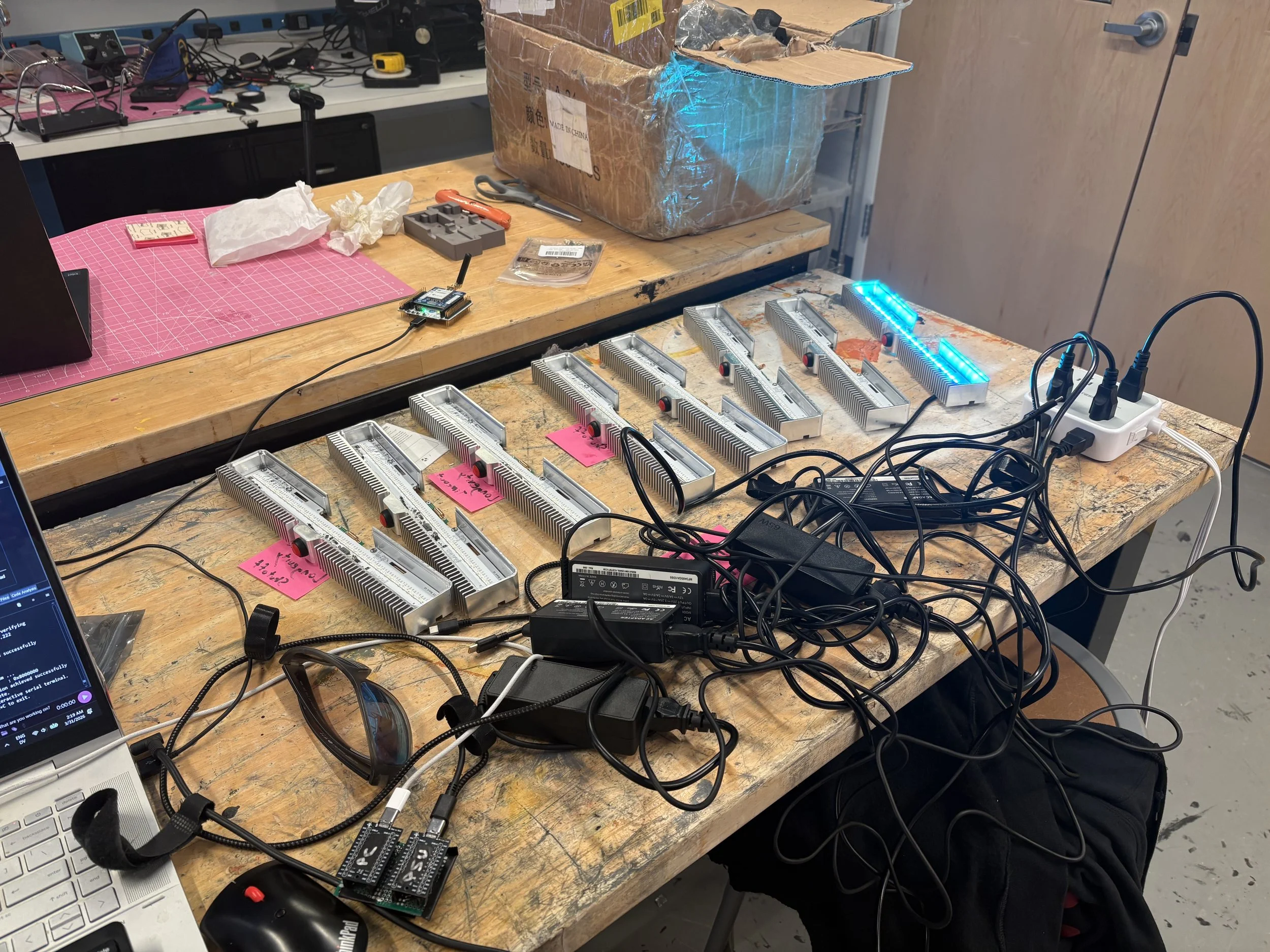
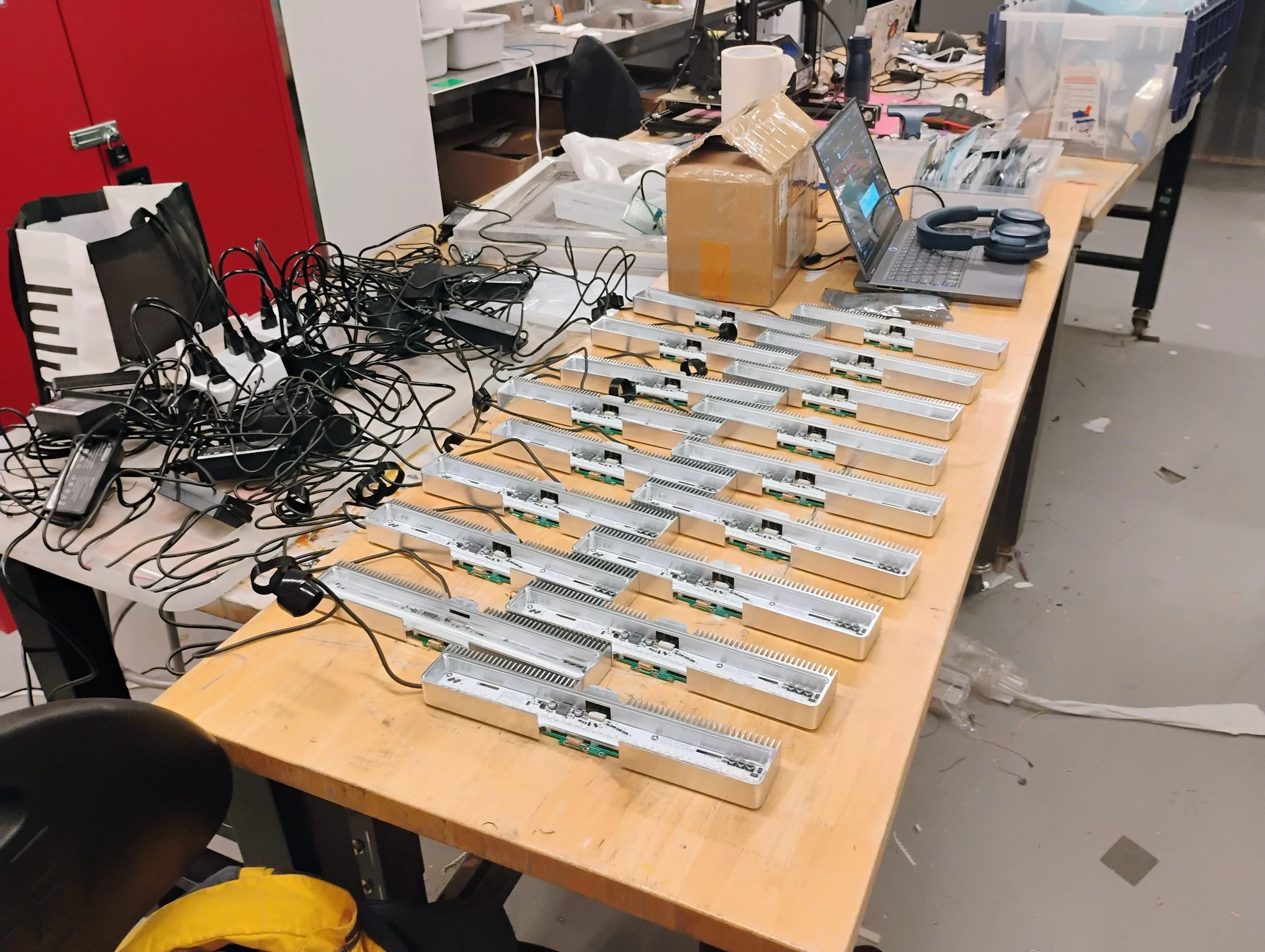
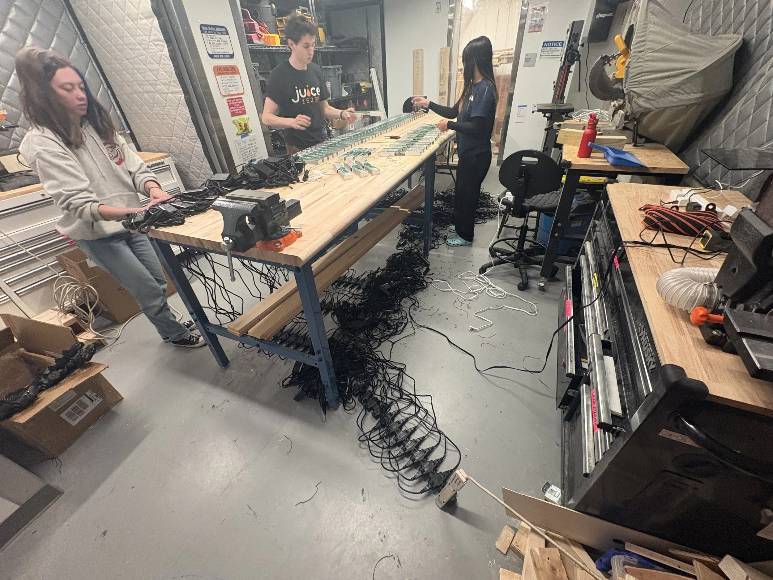
Full scale testing (April 2026):
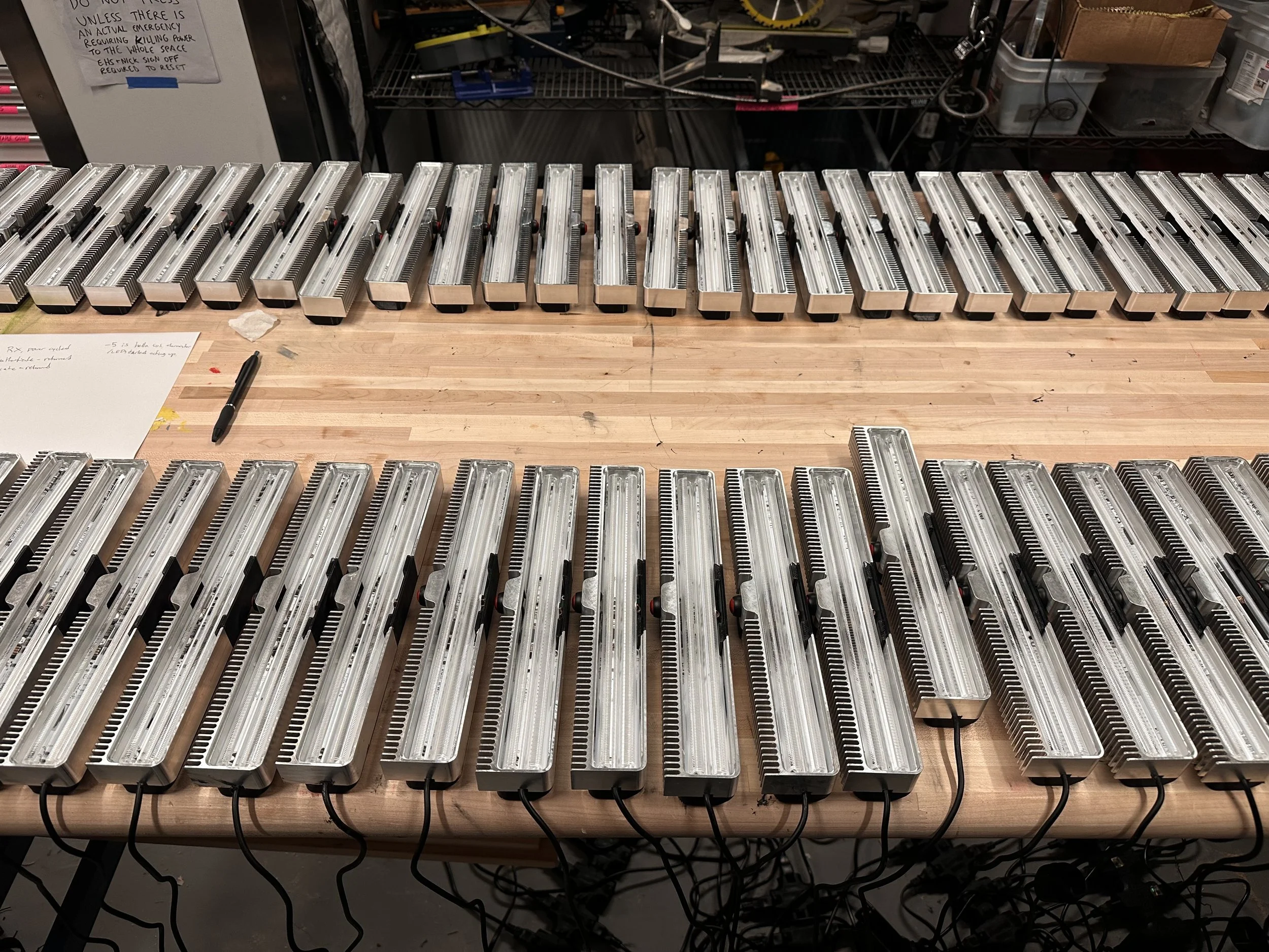
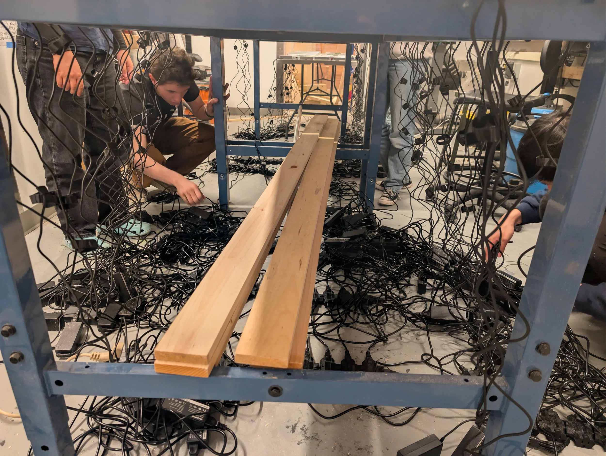
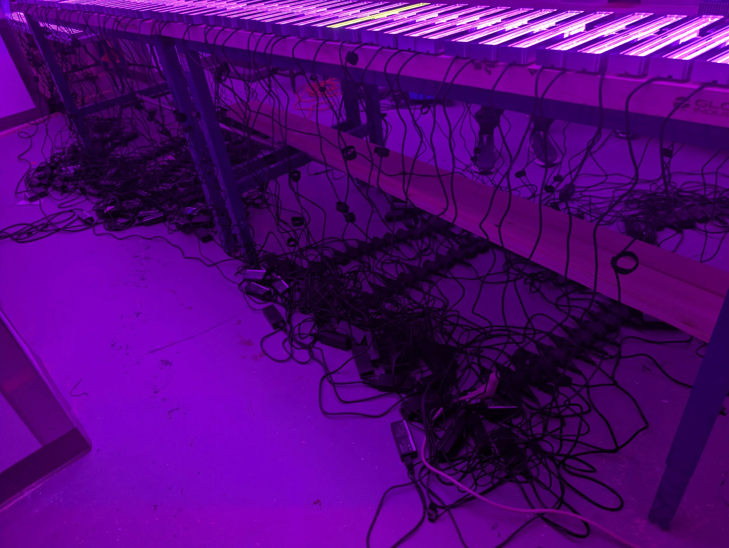
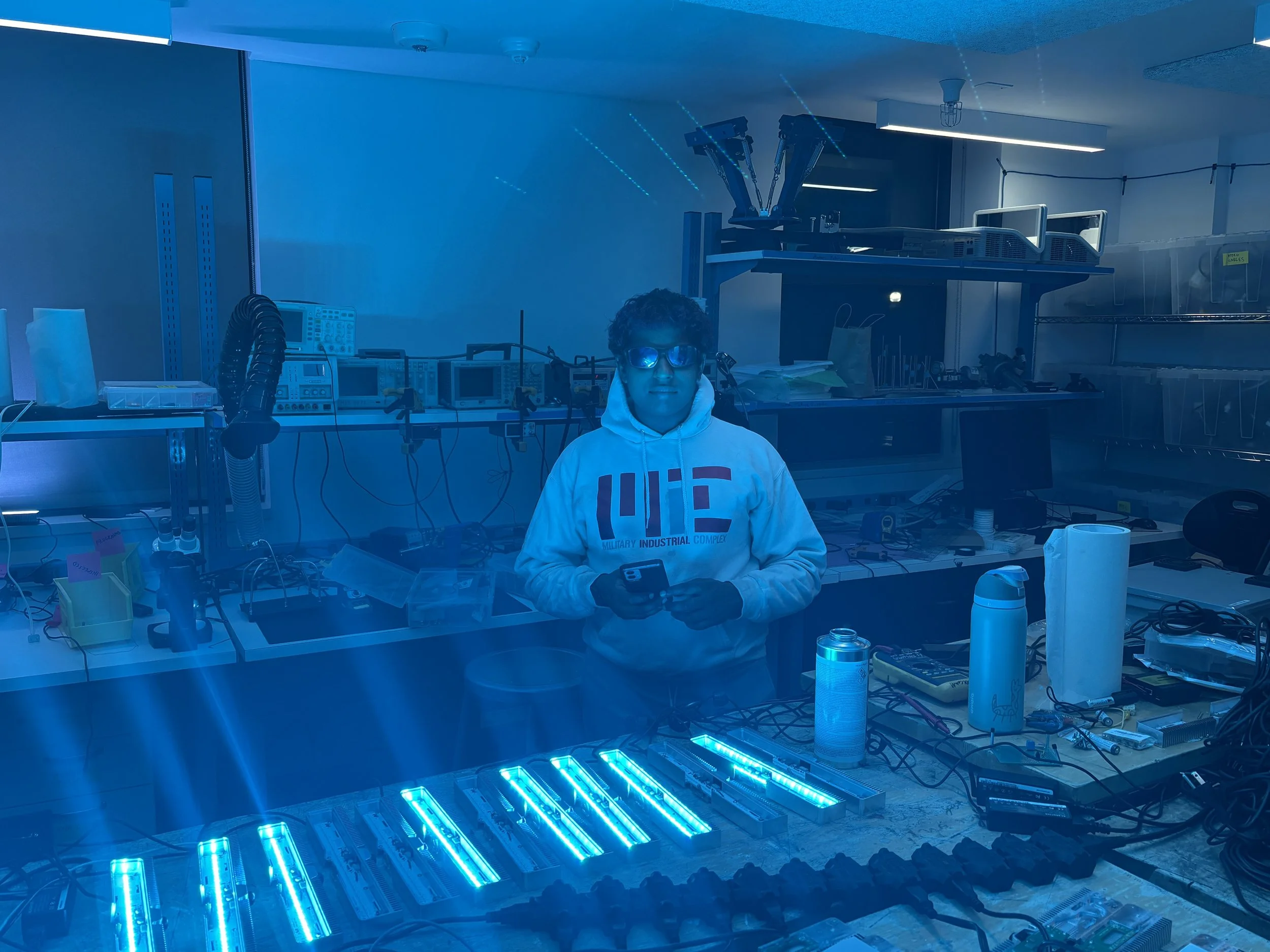
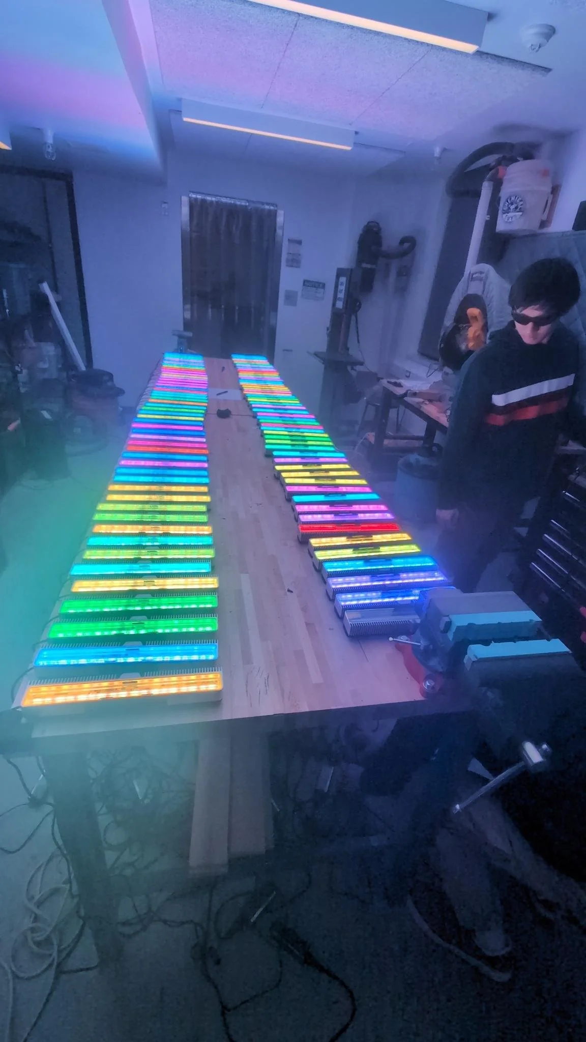
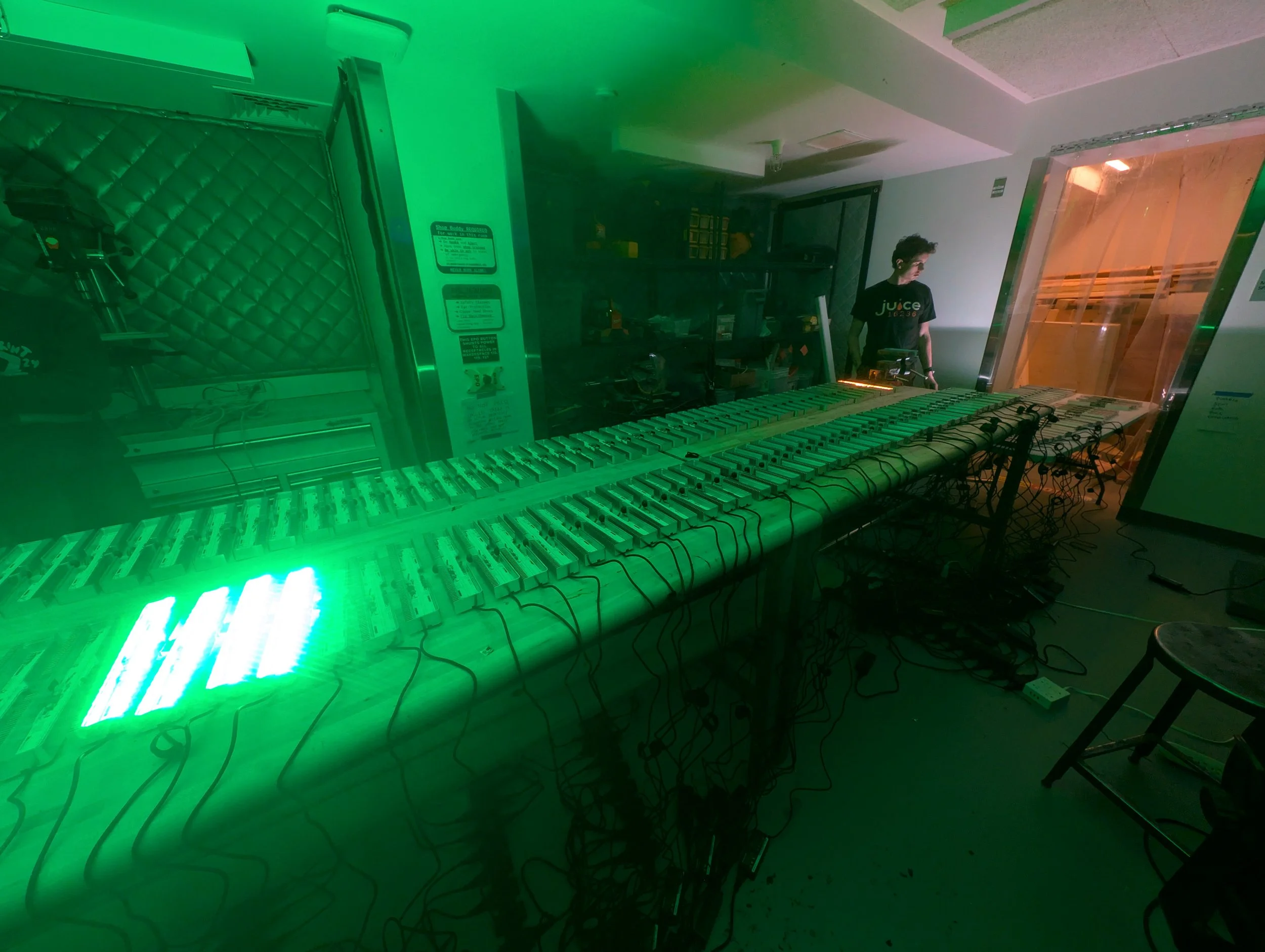
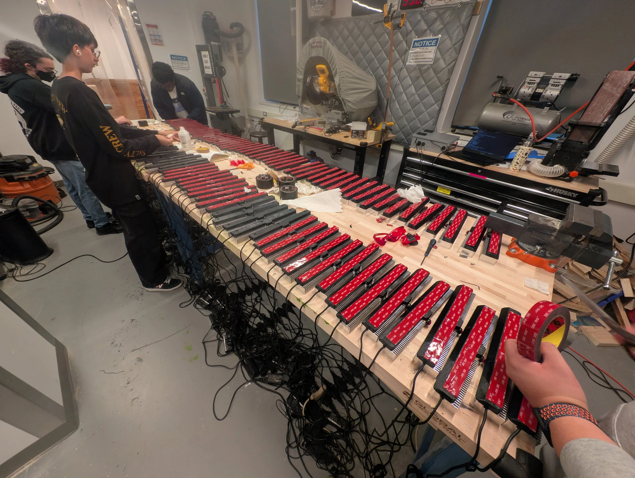
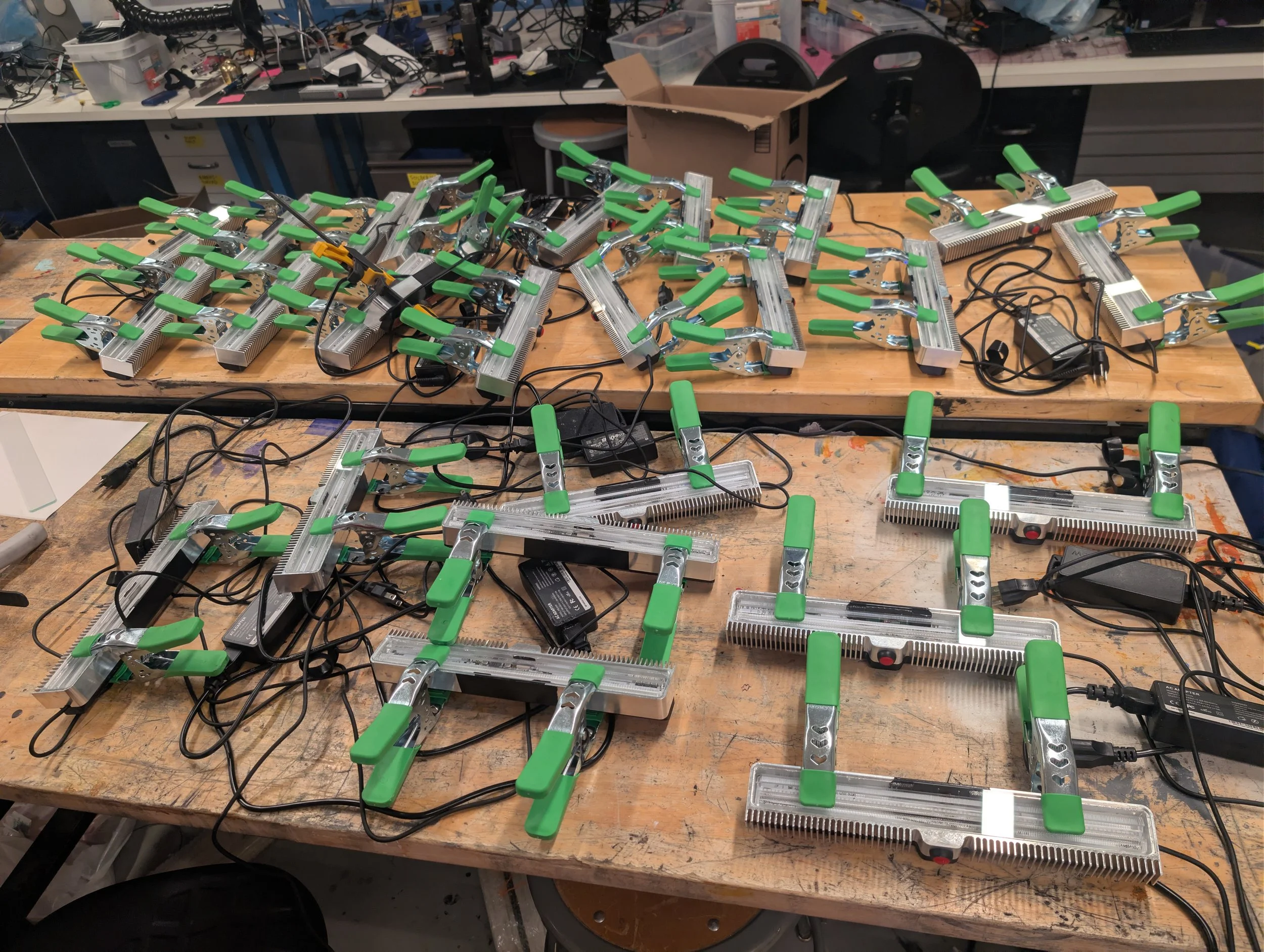
Before gluing and closing up the modules, we ran a number of tests on the entire fleet to ensure that there were no issues with the firmware. All of the modules got laid out consuming all the table space on the makerspace, and six different 120V circuits. At peak power output during the testing, we were pumping almost 10 kW of energy into that room, and it became noticeably warmer than the rest of the makerspace.
Mass production part 2 (April 2026):
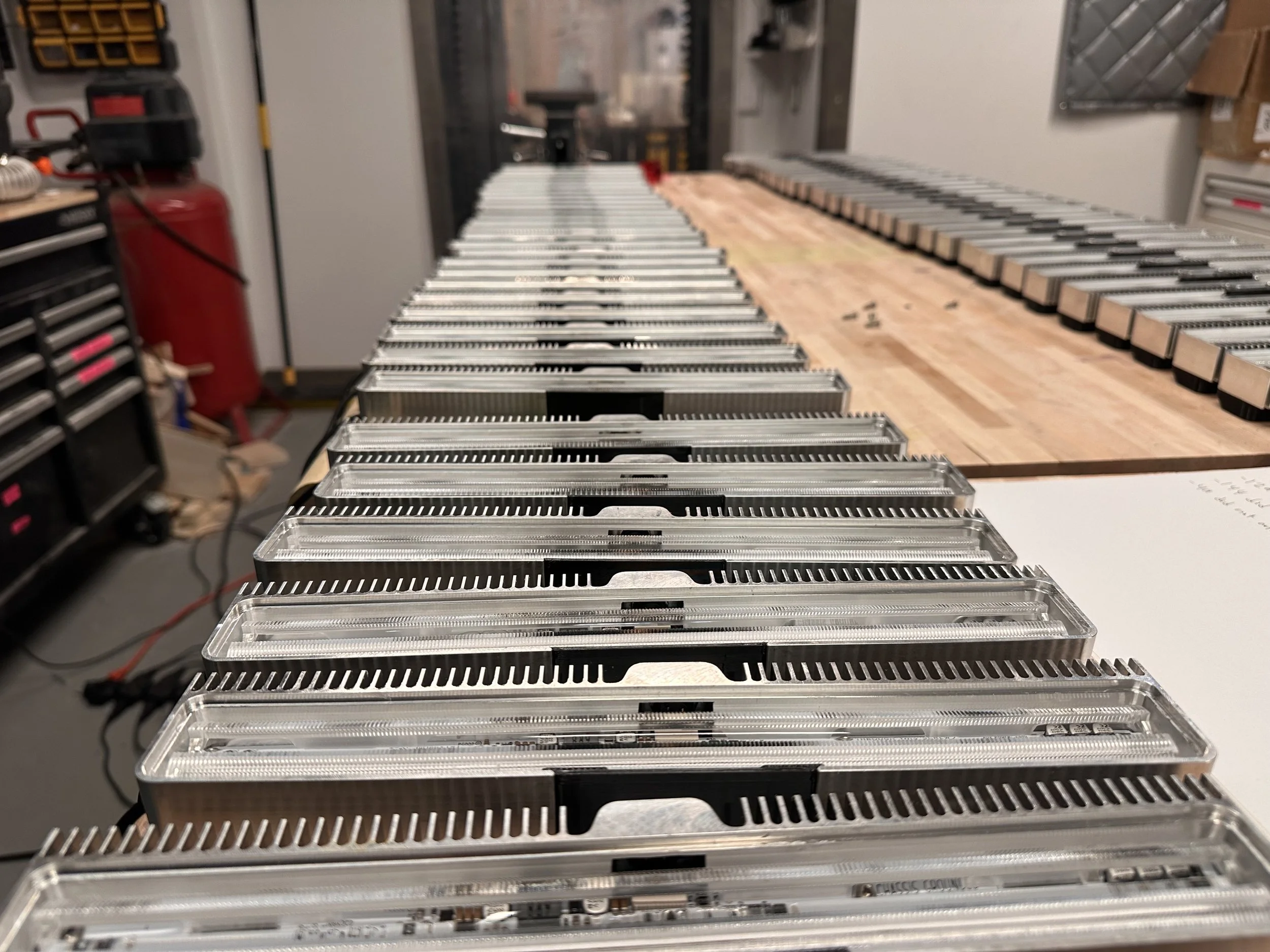
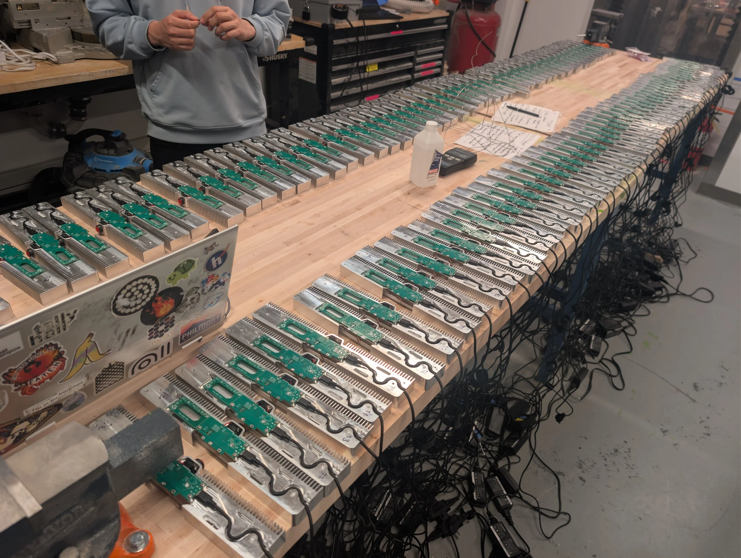
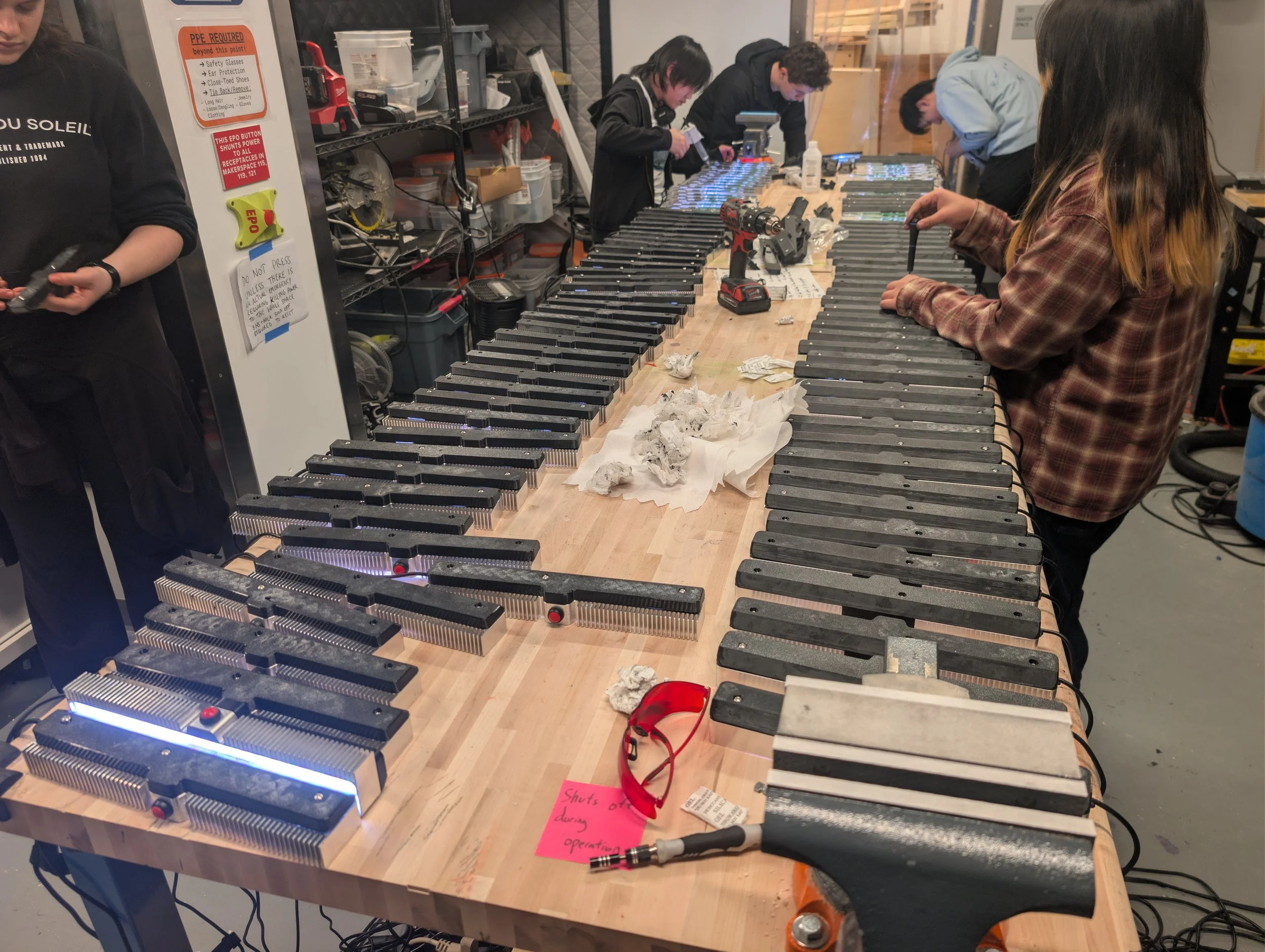
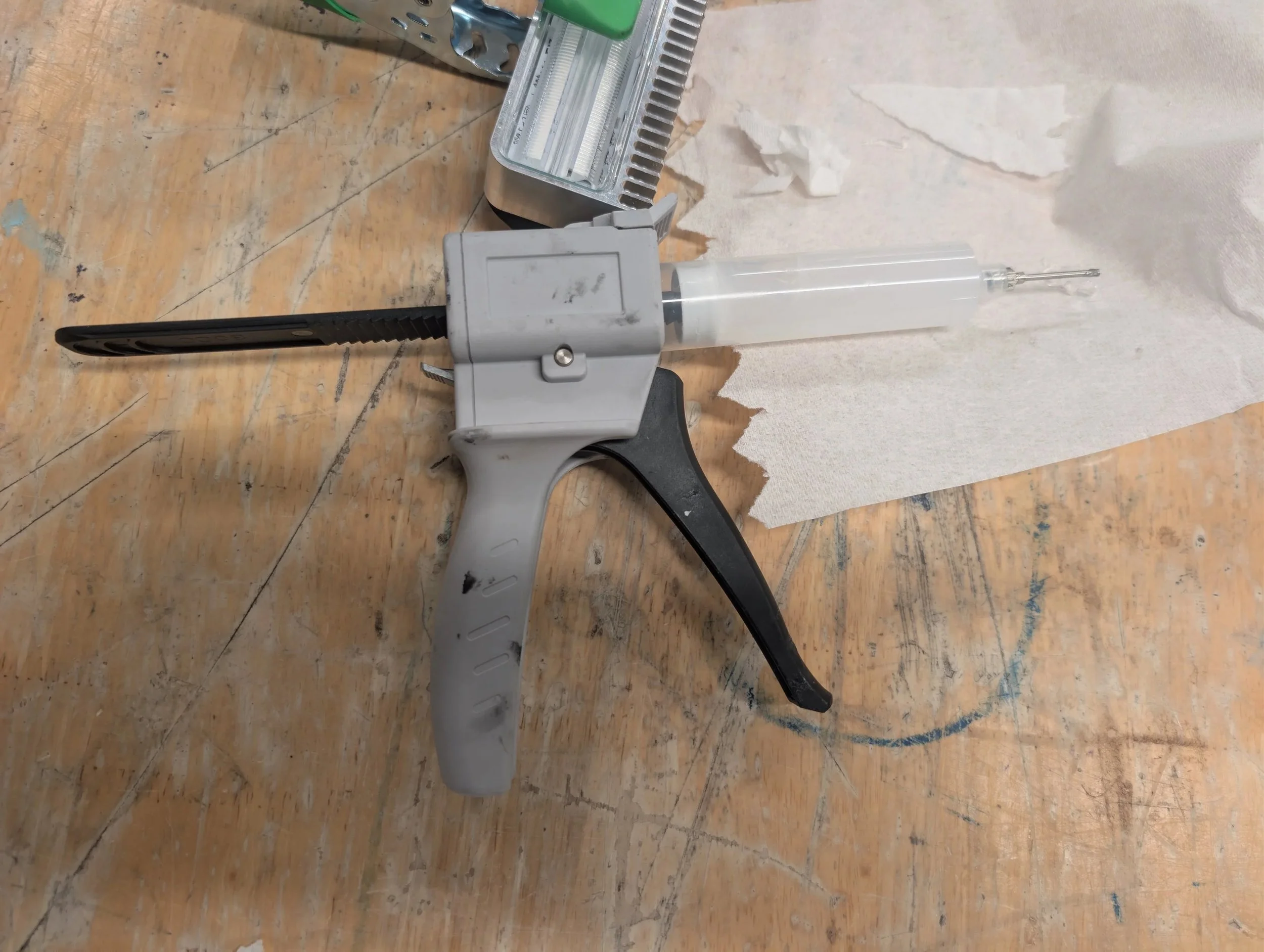
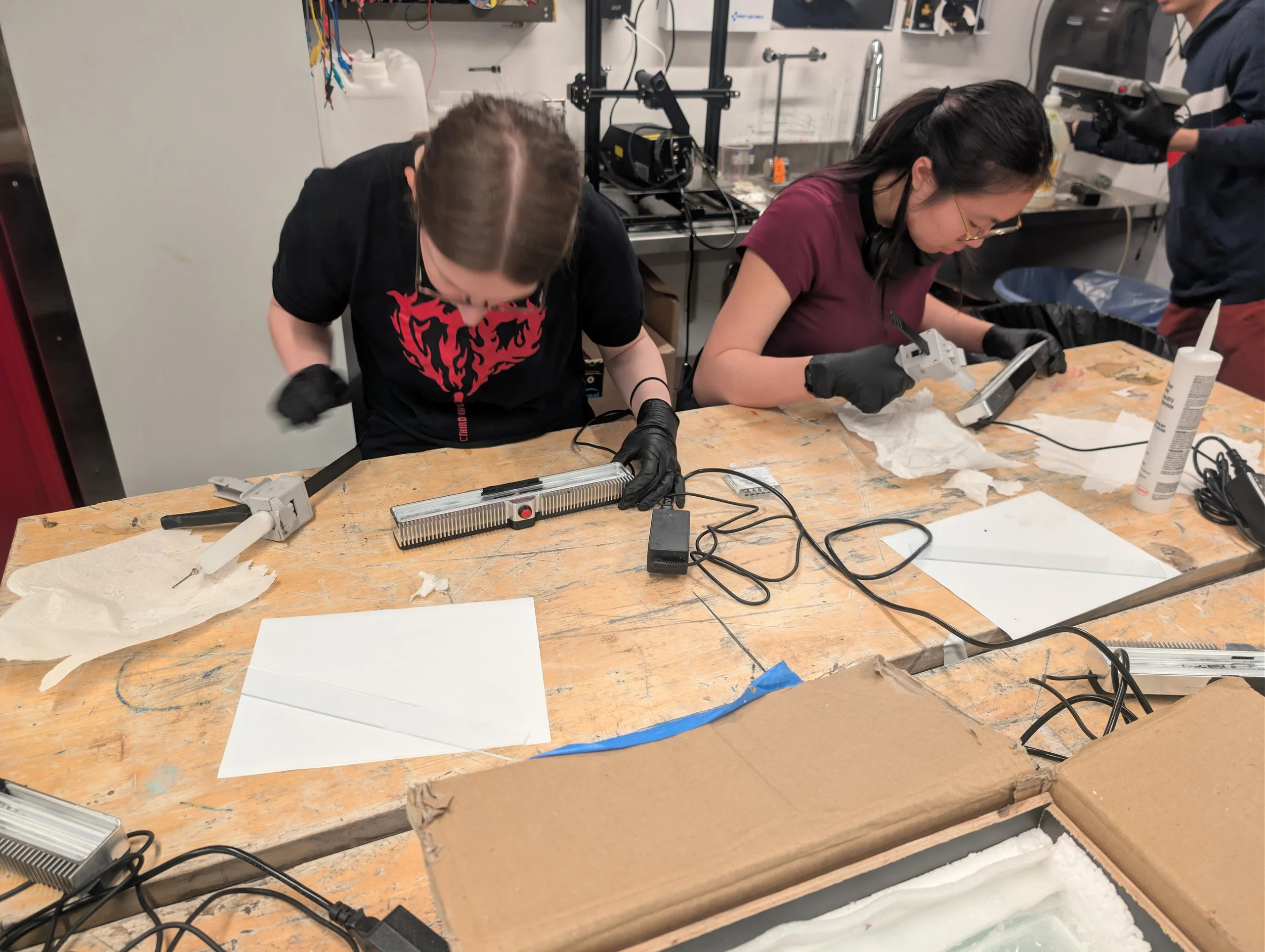
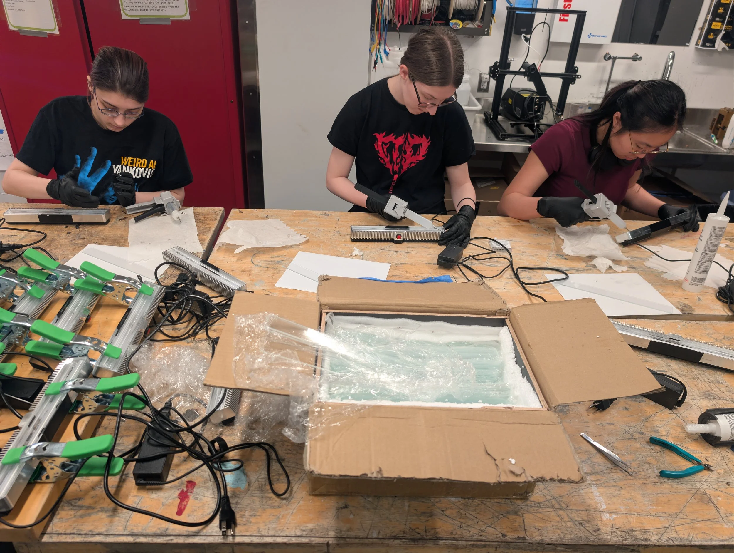
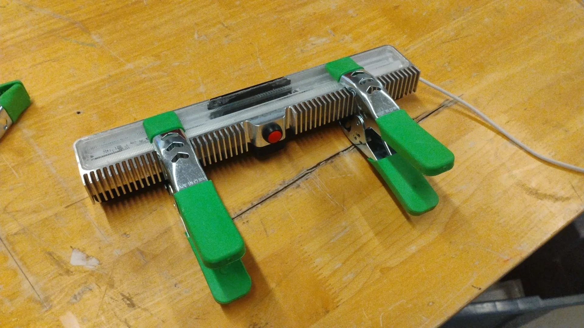
Once we were satisfied that the firmware was working as expected, we set about closing each of the modules up. We used silicone caulk around the glass and power supply cable to make a watertight seal, and applied VHB tape to the underside to mount them to the windowsill.
Deploy (April 2026):
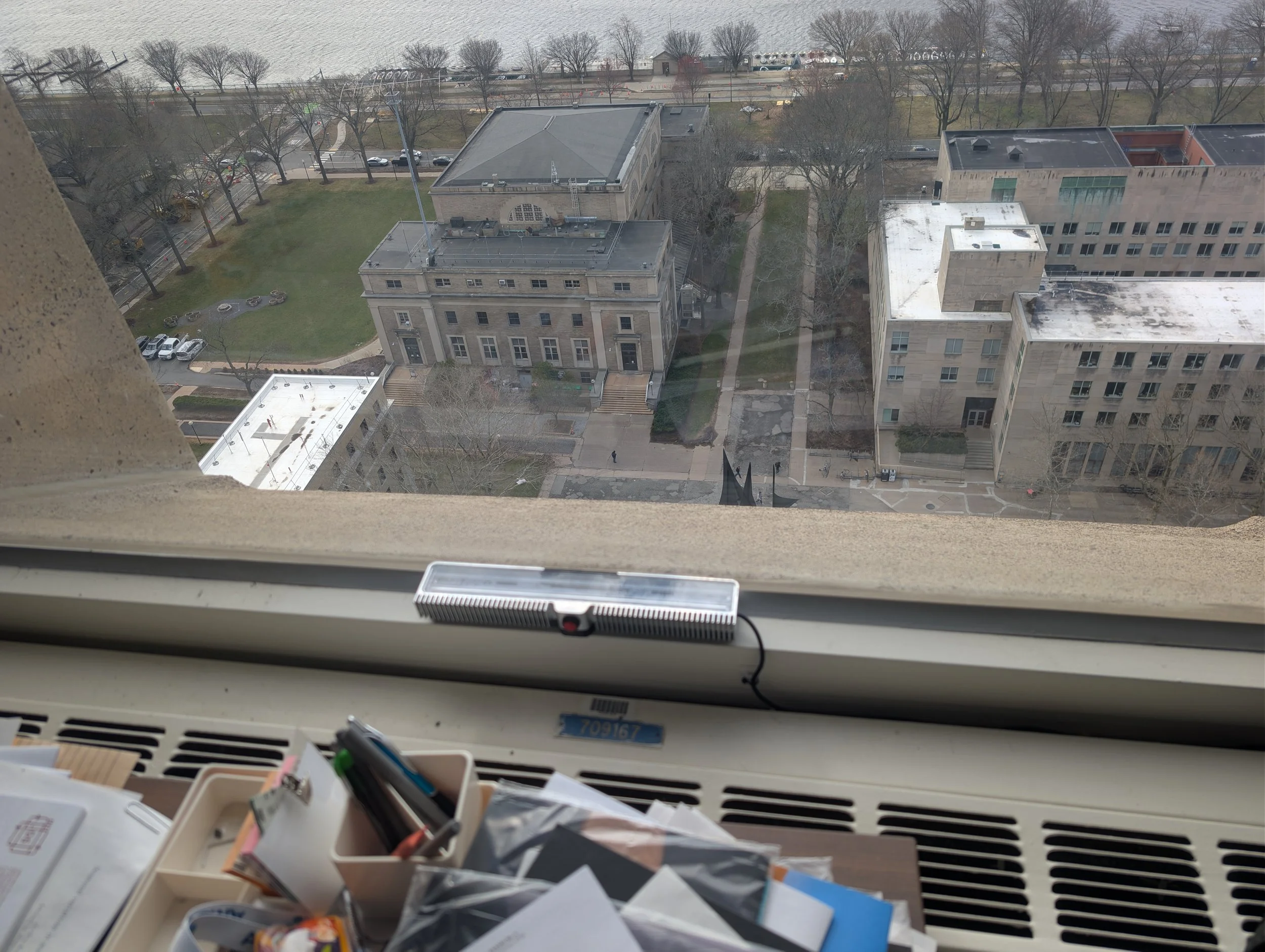
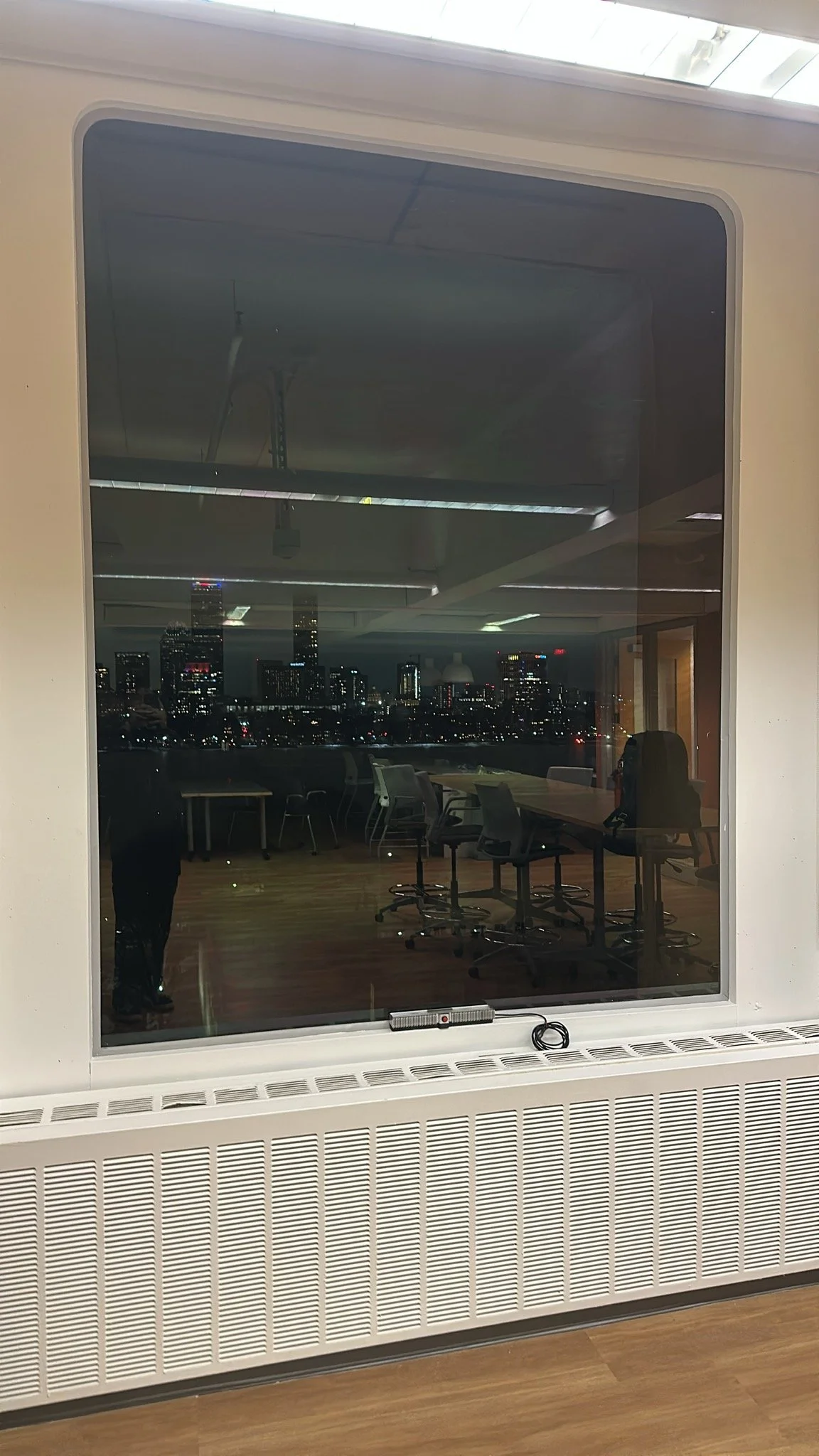
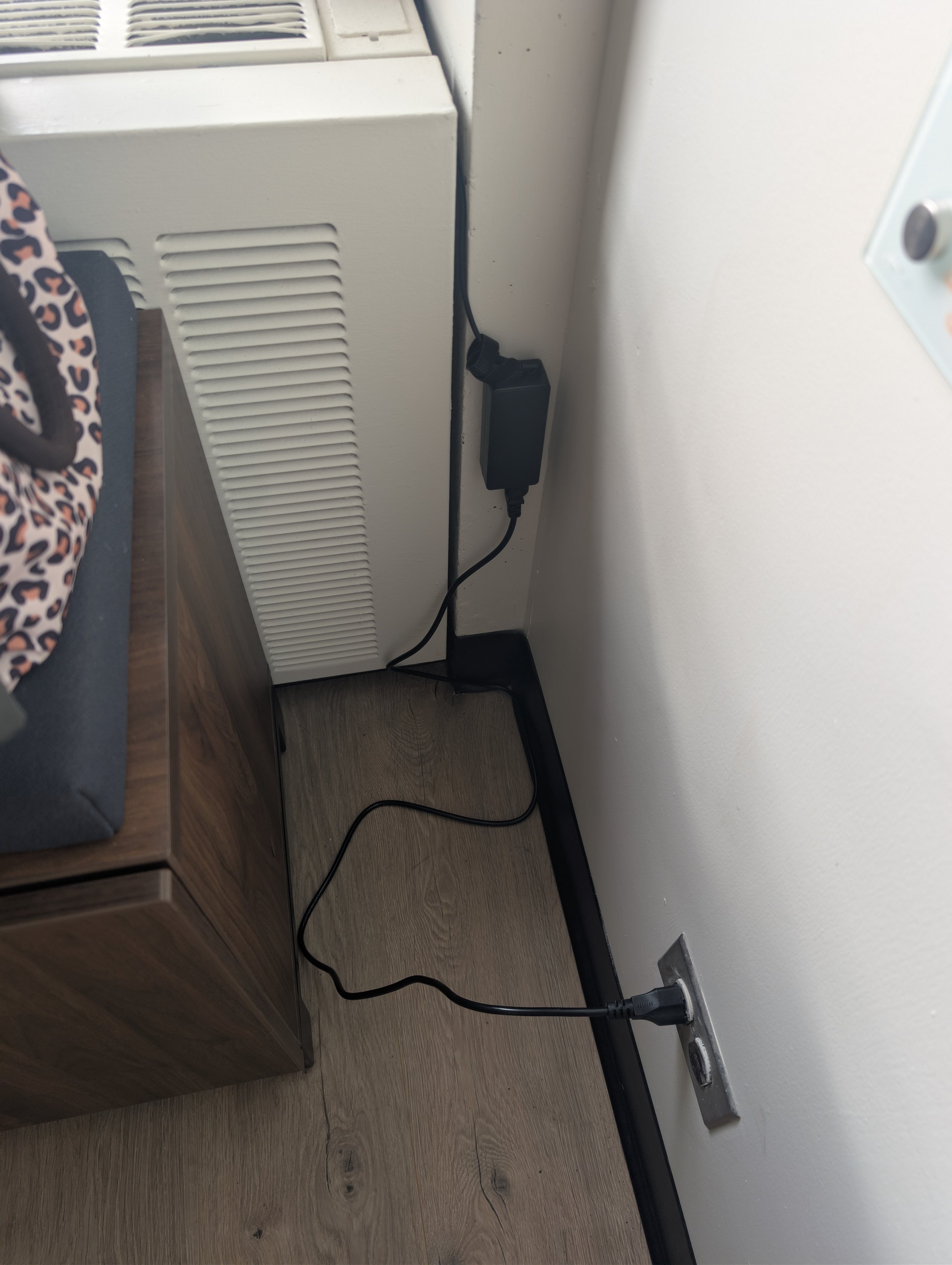
After mass production week, it was time to install a module in each of the windows in the Green Building. At the beginning of the project we spoke with EAPS staff and faculty to get permission for the installation, and during this week a member of the facilities staff accompanied us every day from 8am – 11am opening each of the rooms for us to conduct installation.
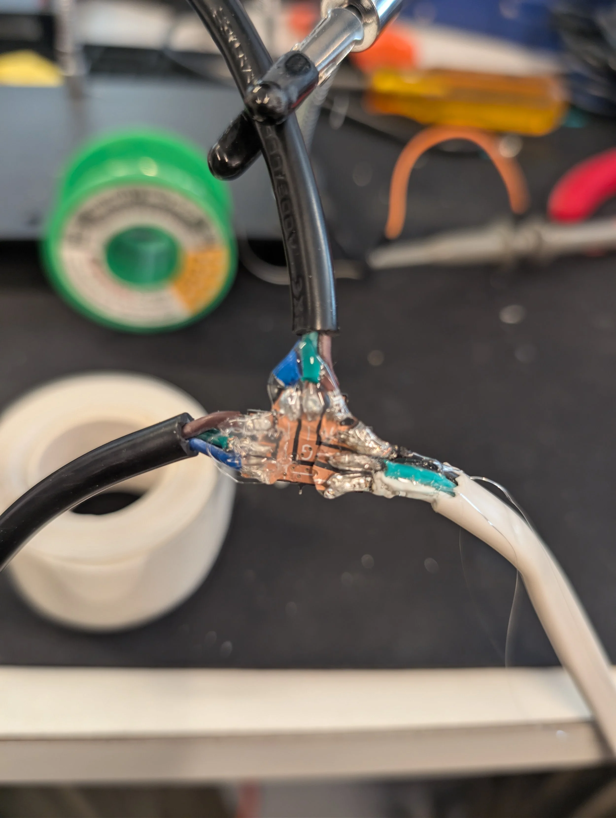
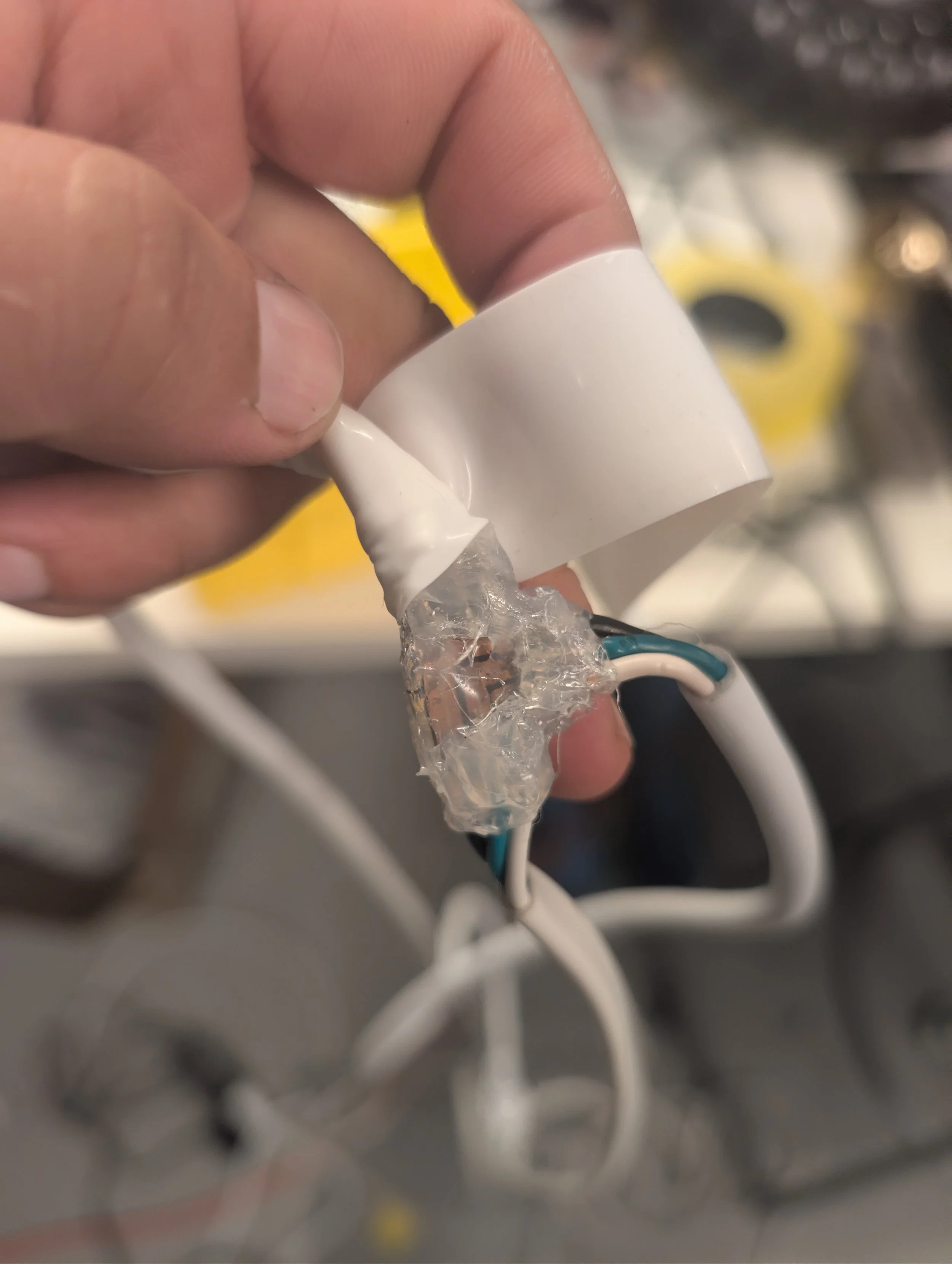
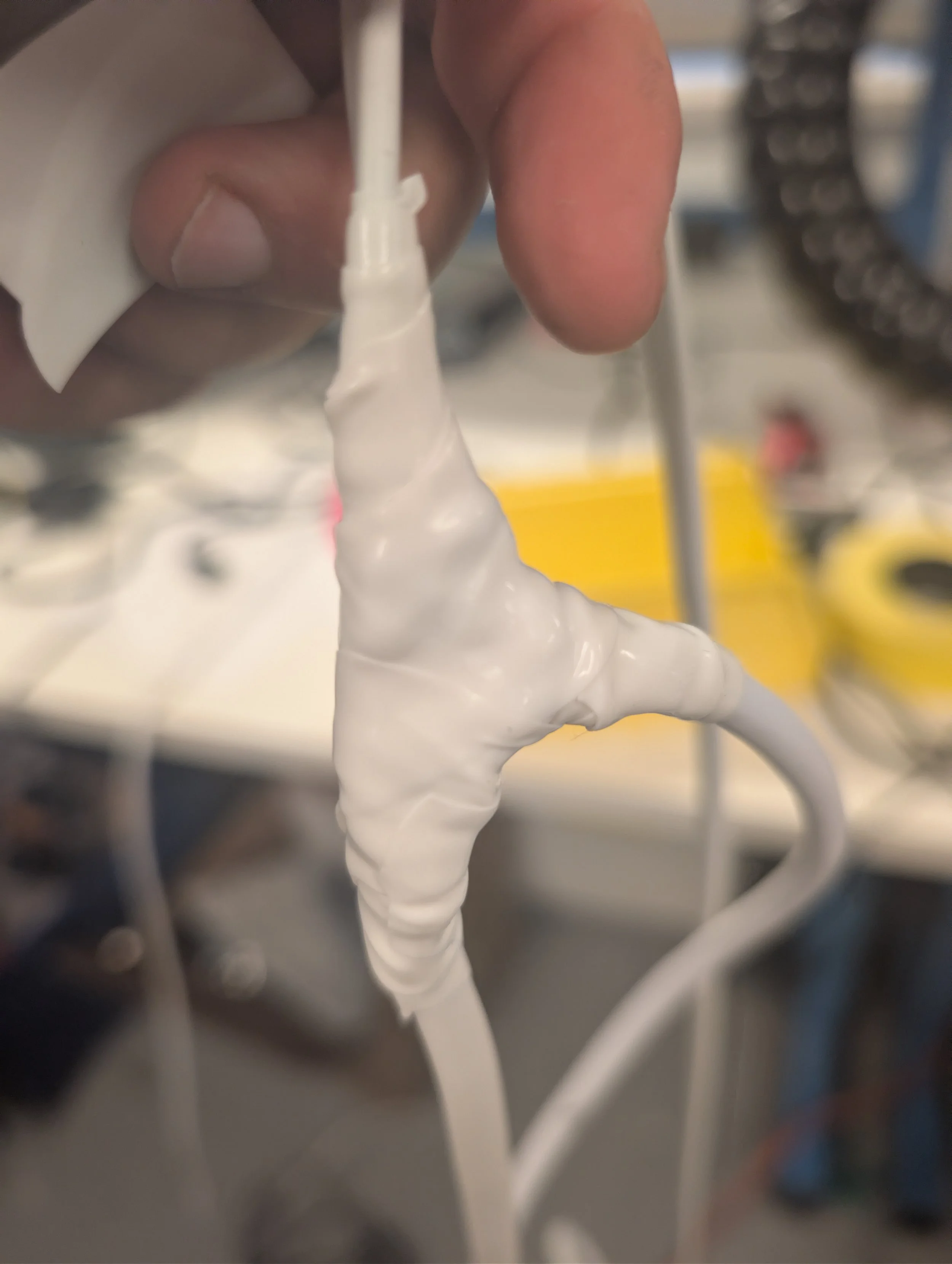
For some rooms with multiple windows only reachable via one power outlet, we made custom extension cables with multiple branches to run along all the windows.
Reveal (April 2026):
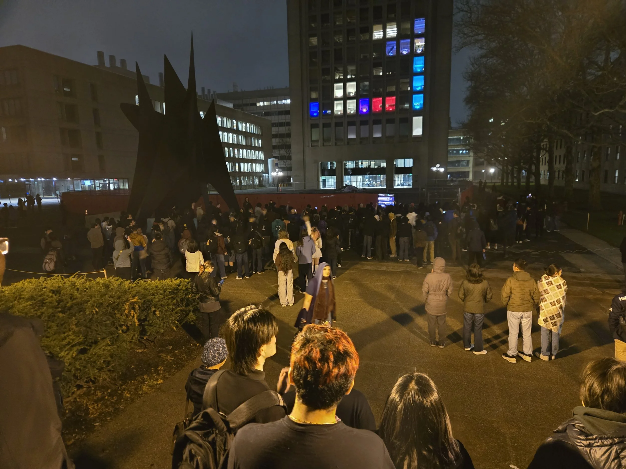
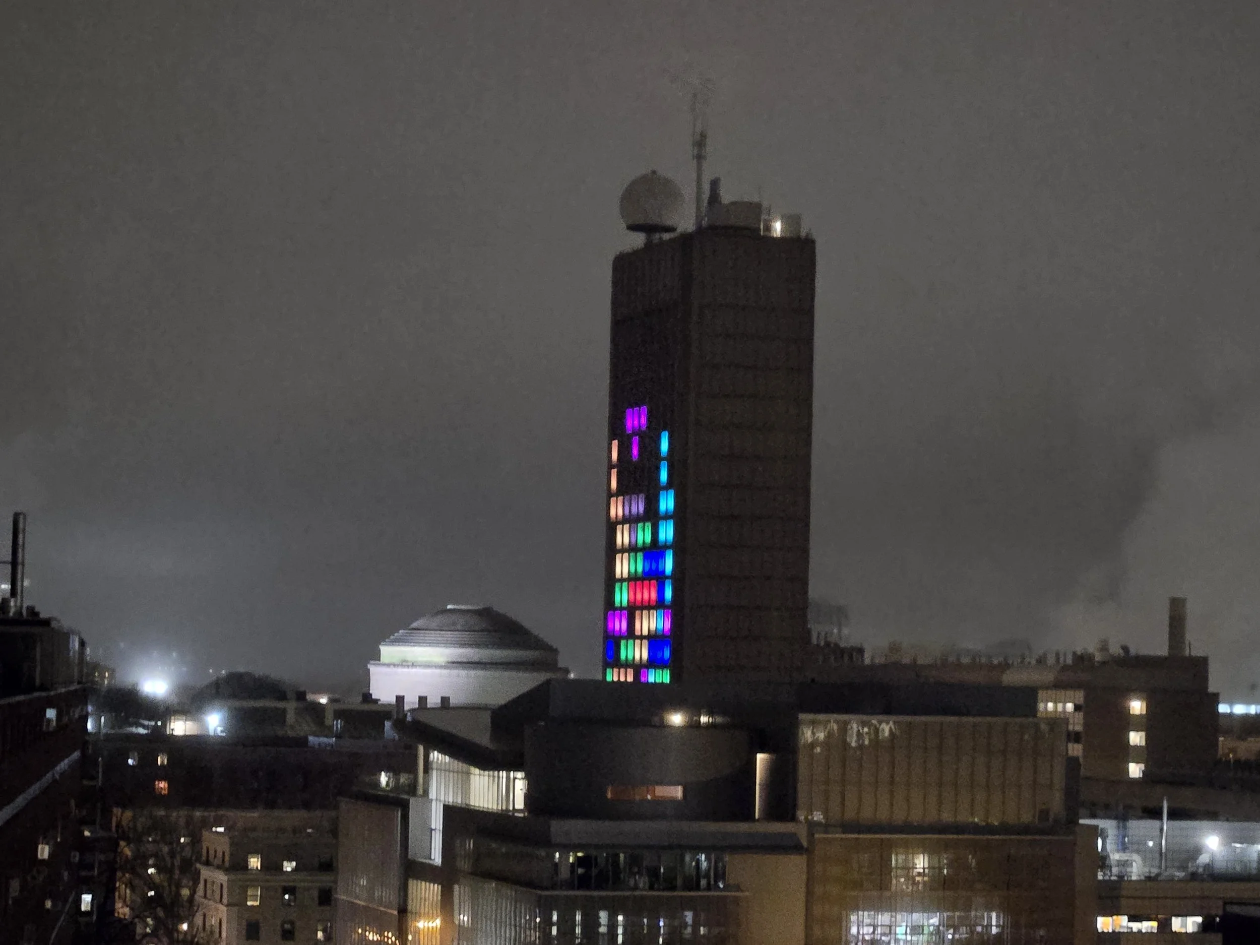
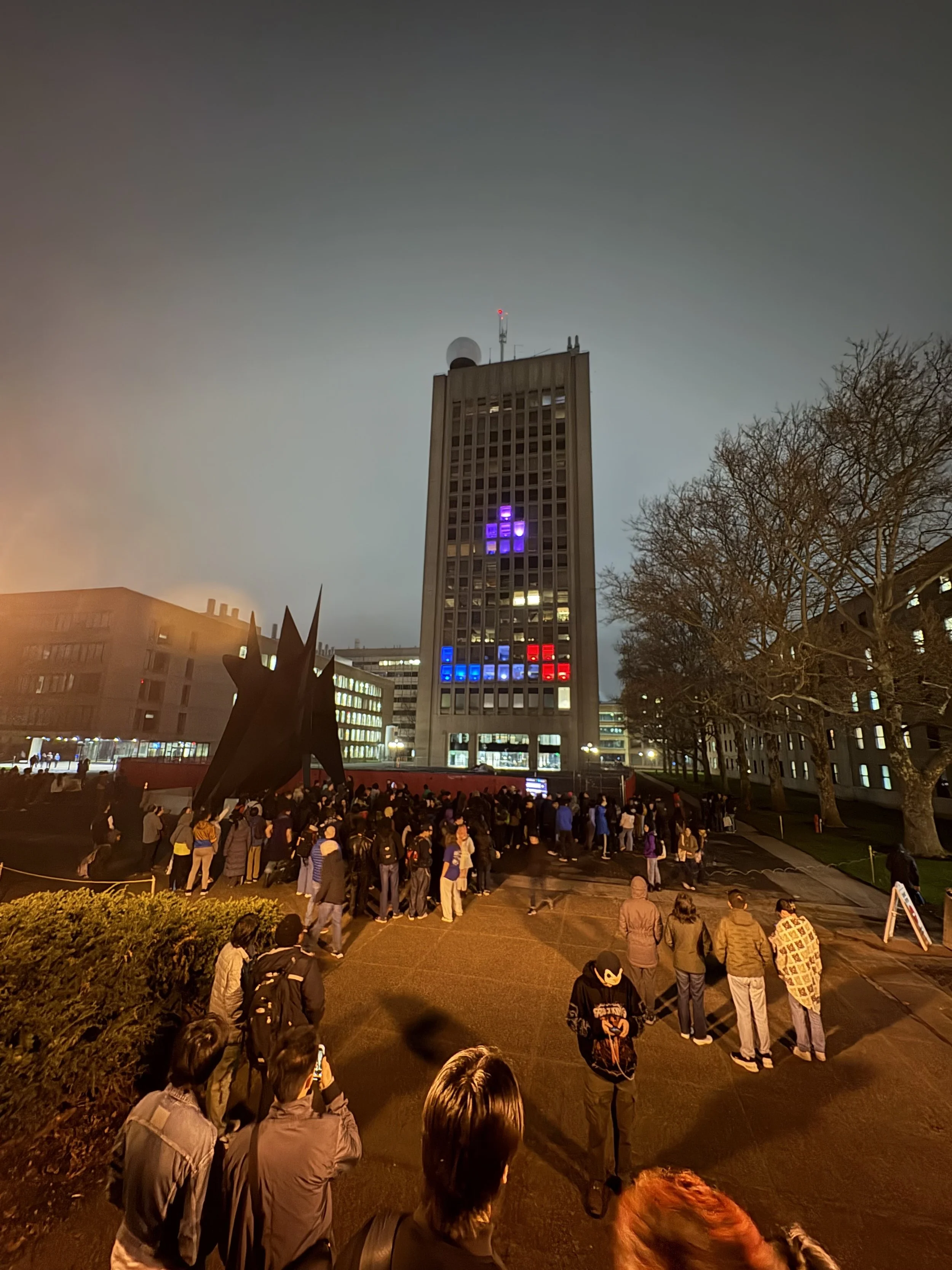
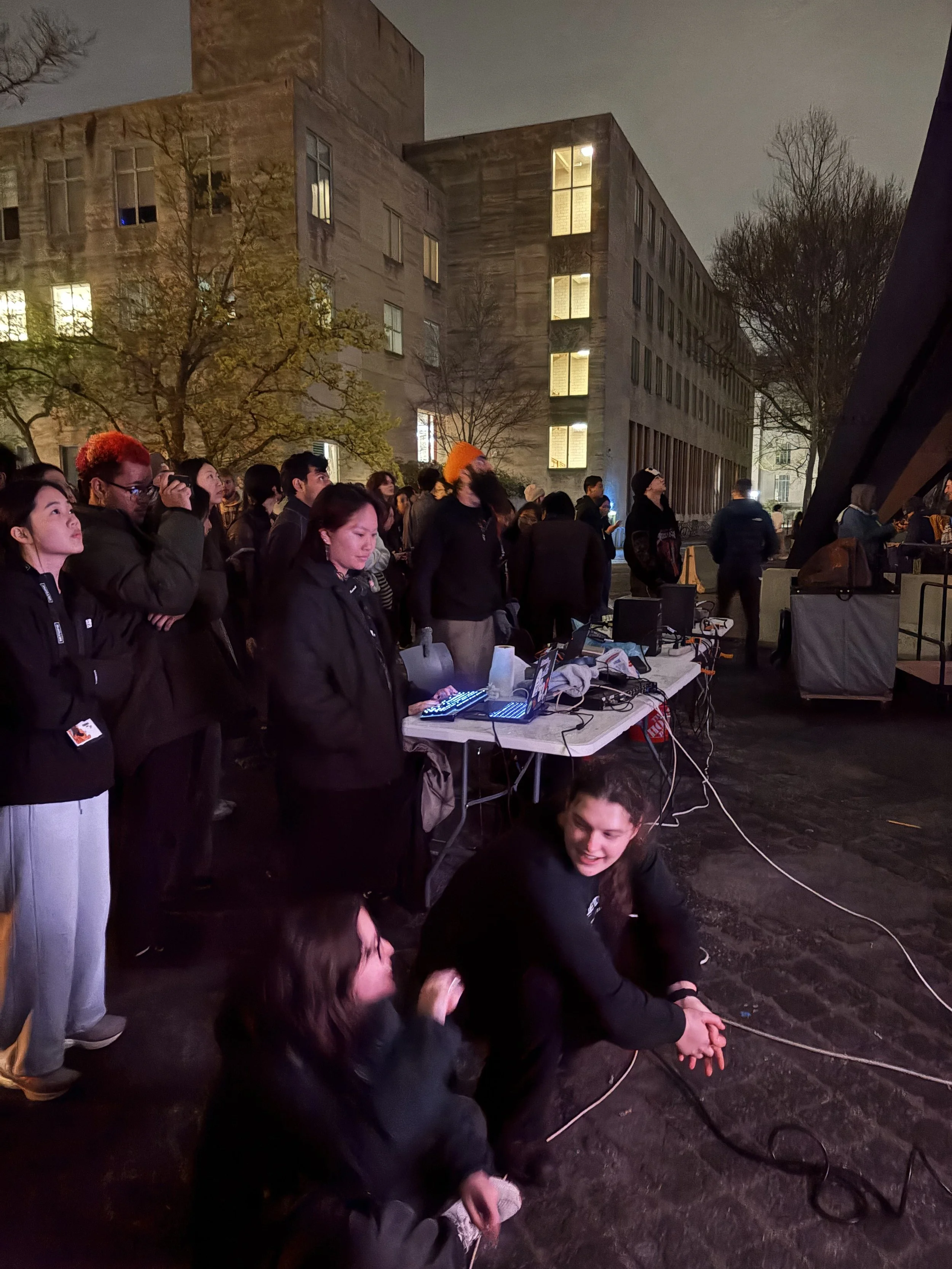
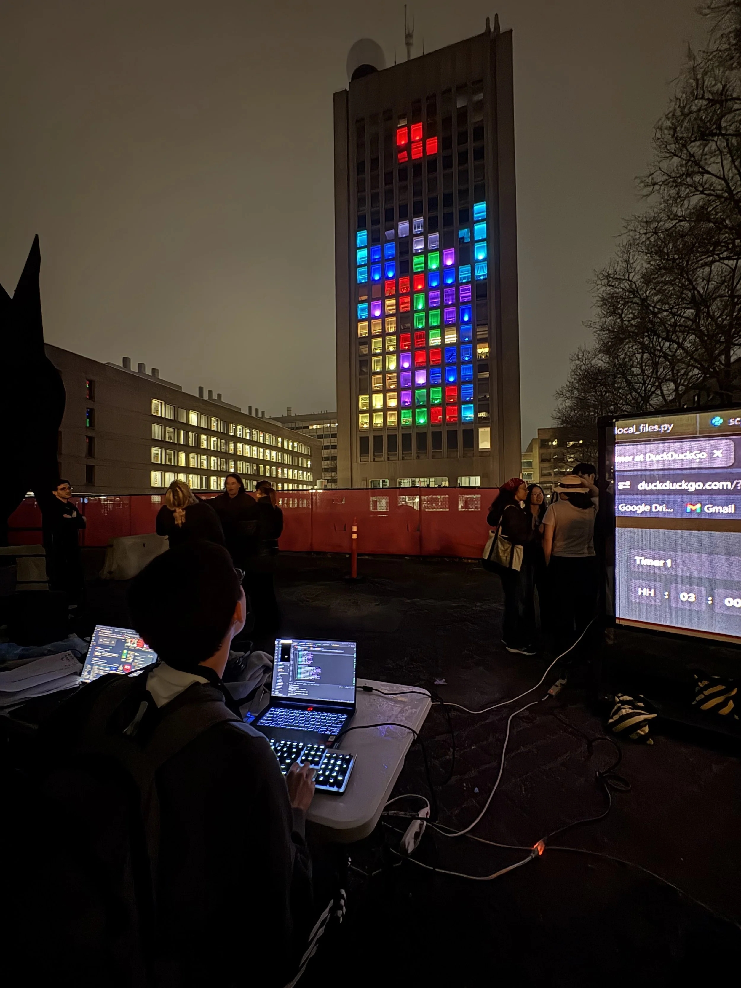
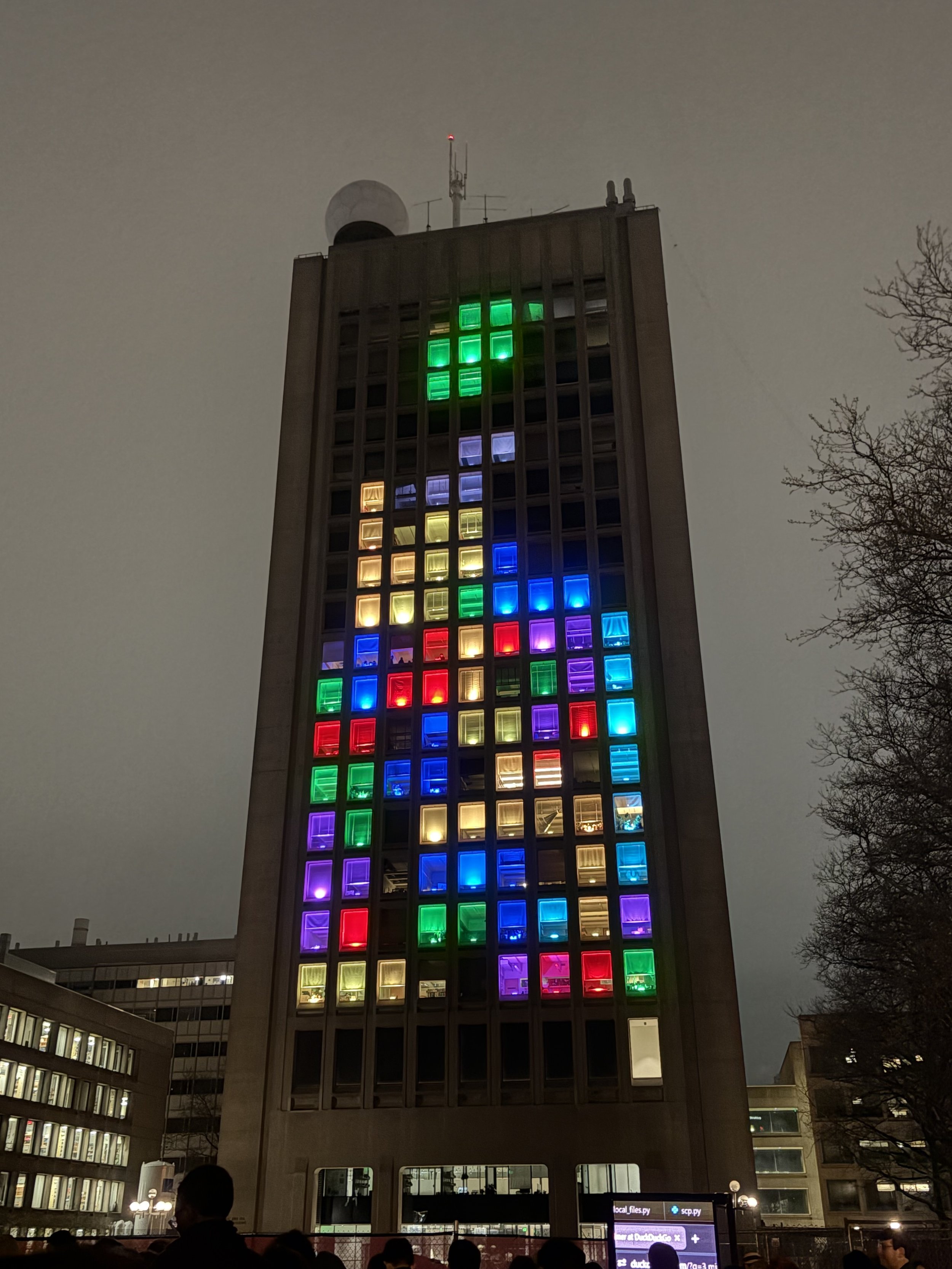
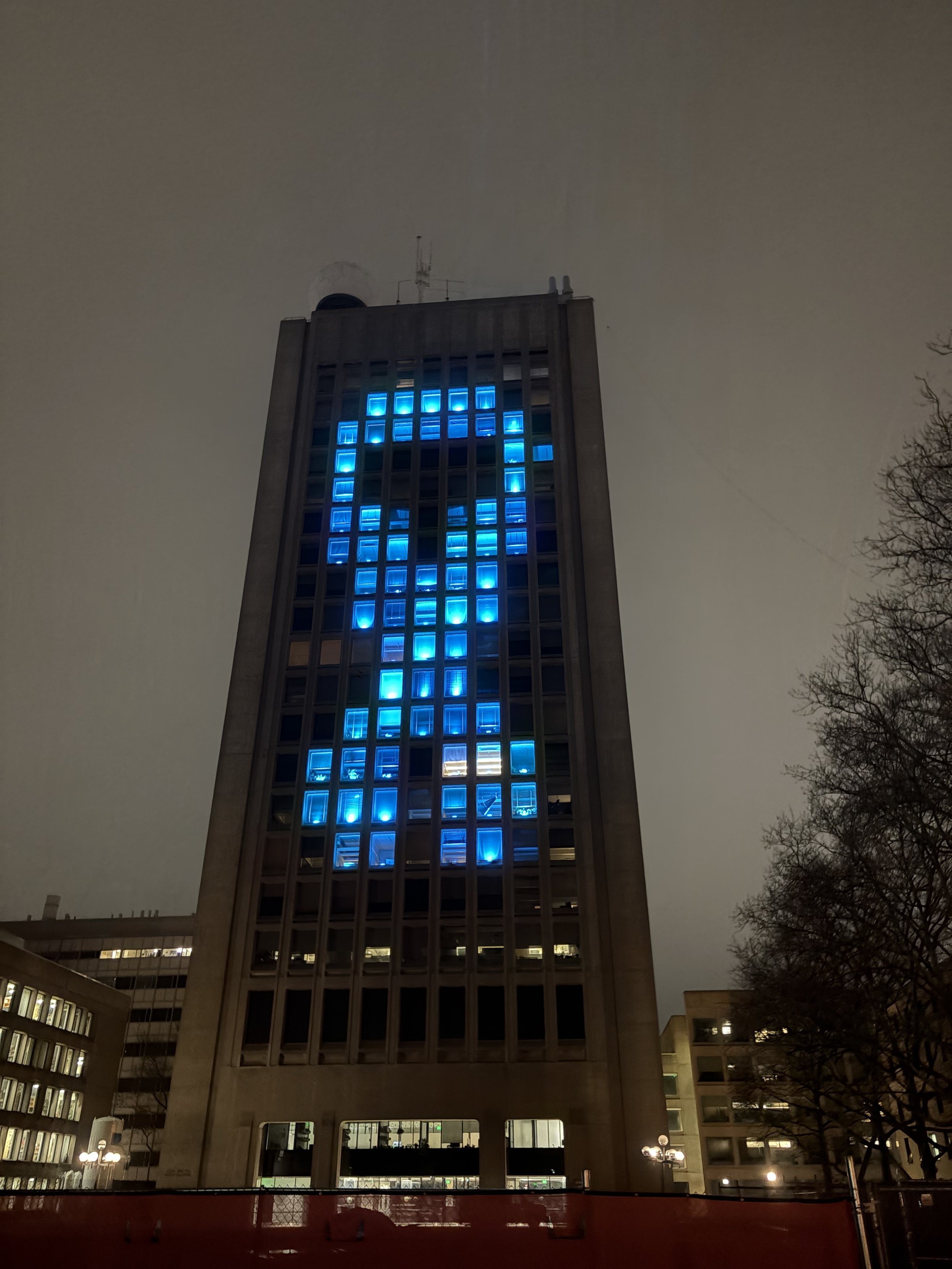
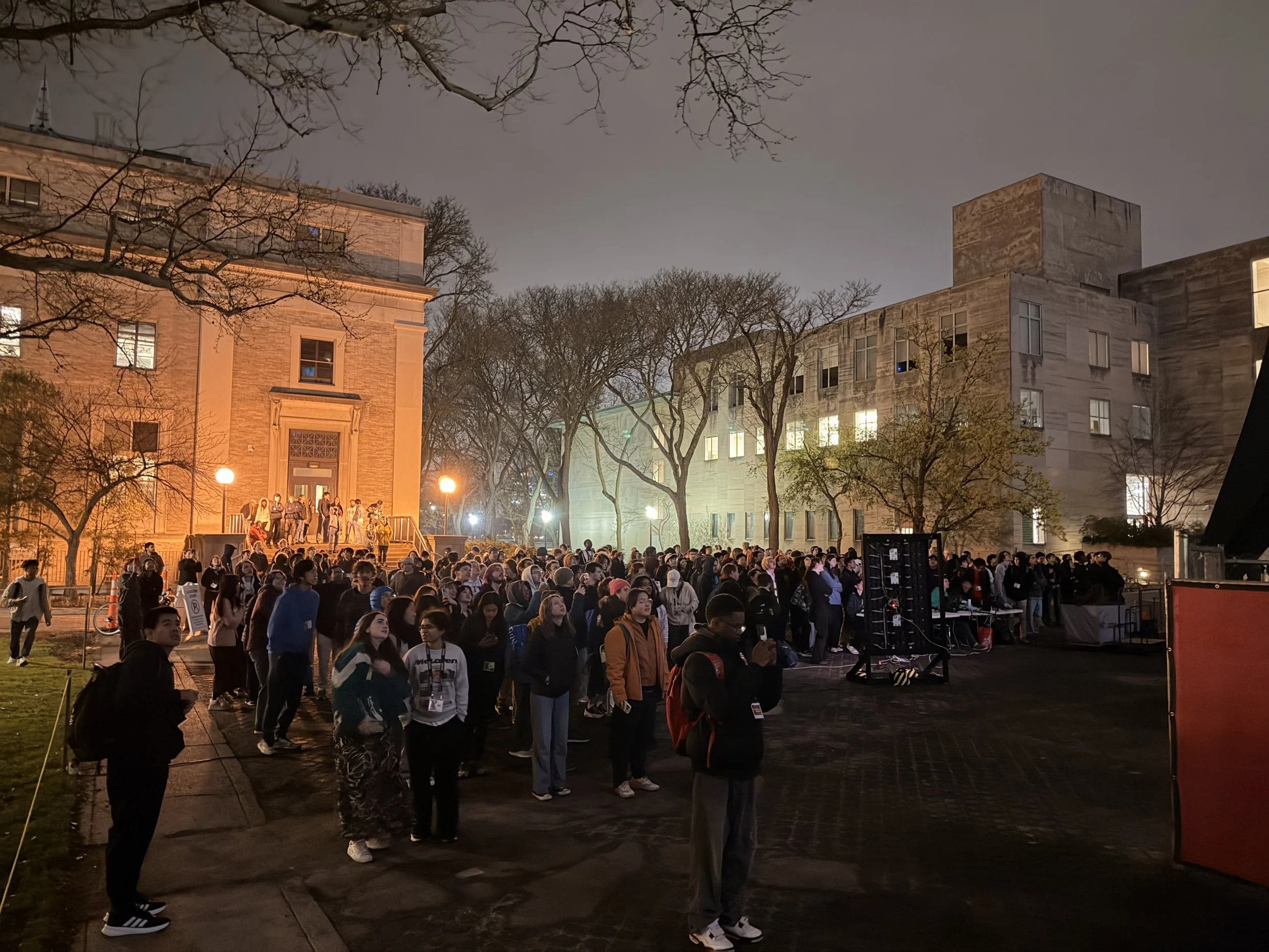
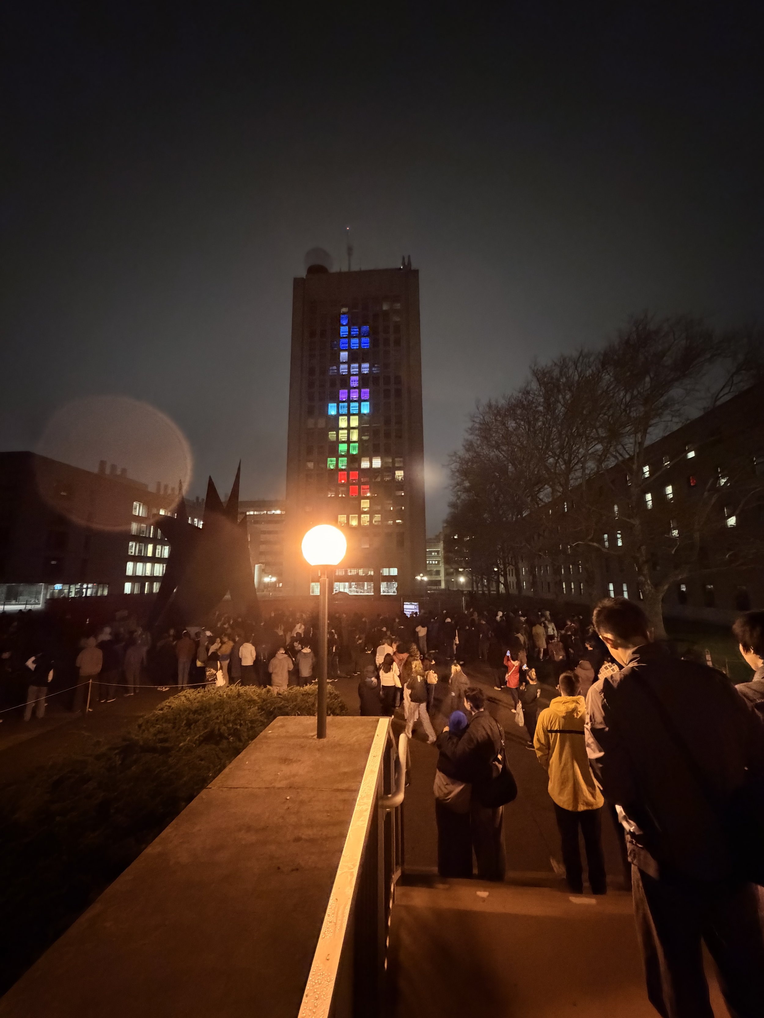
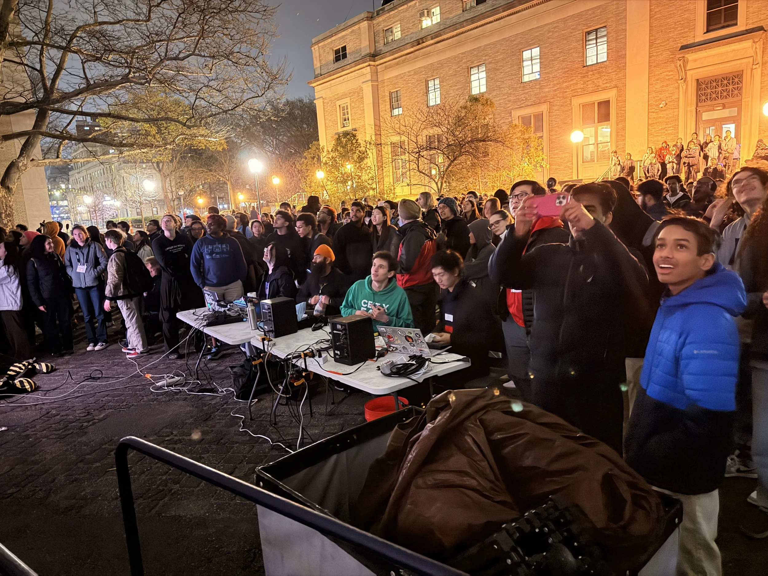
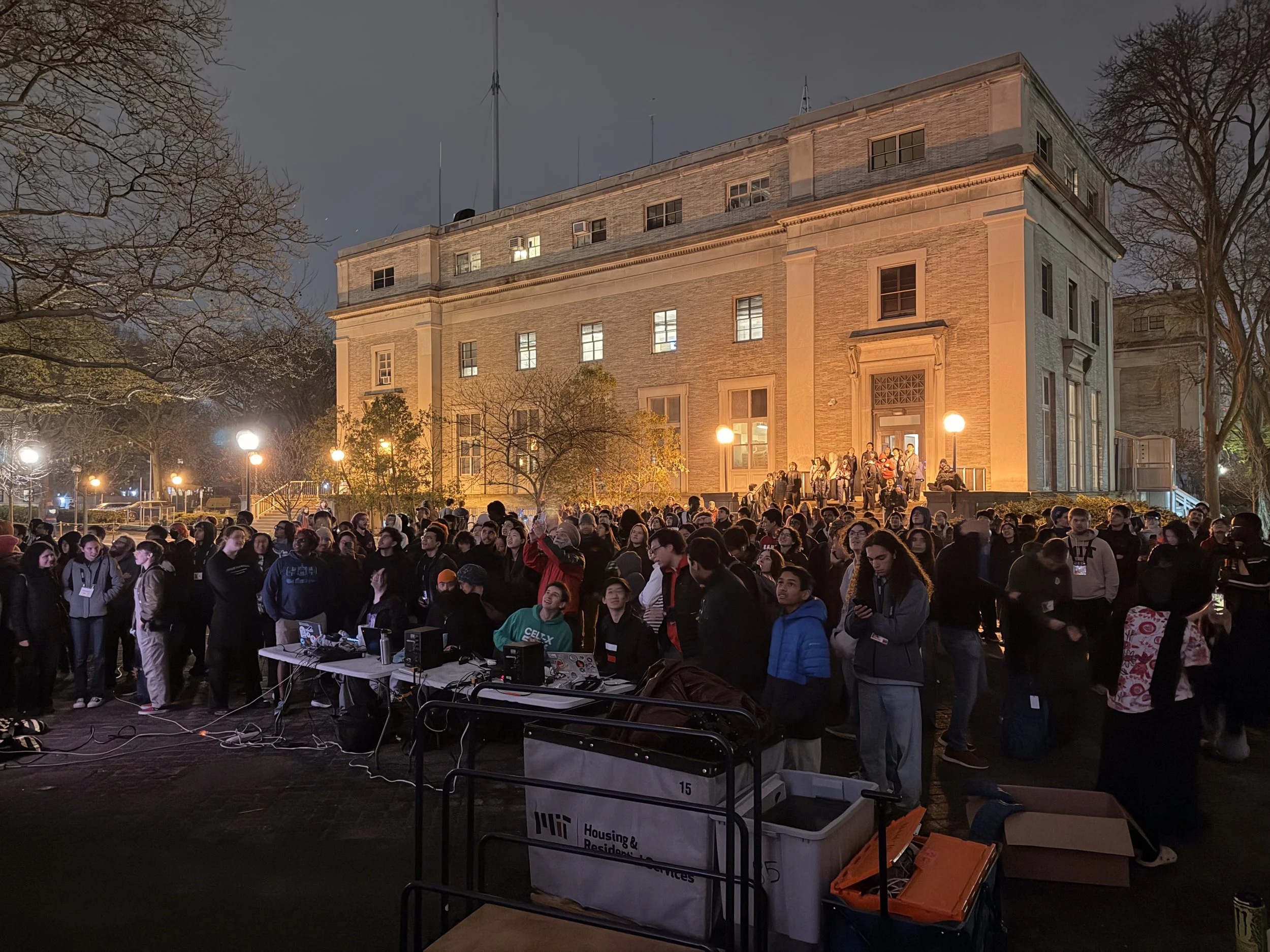
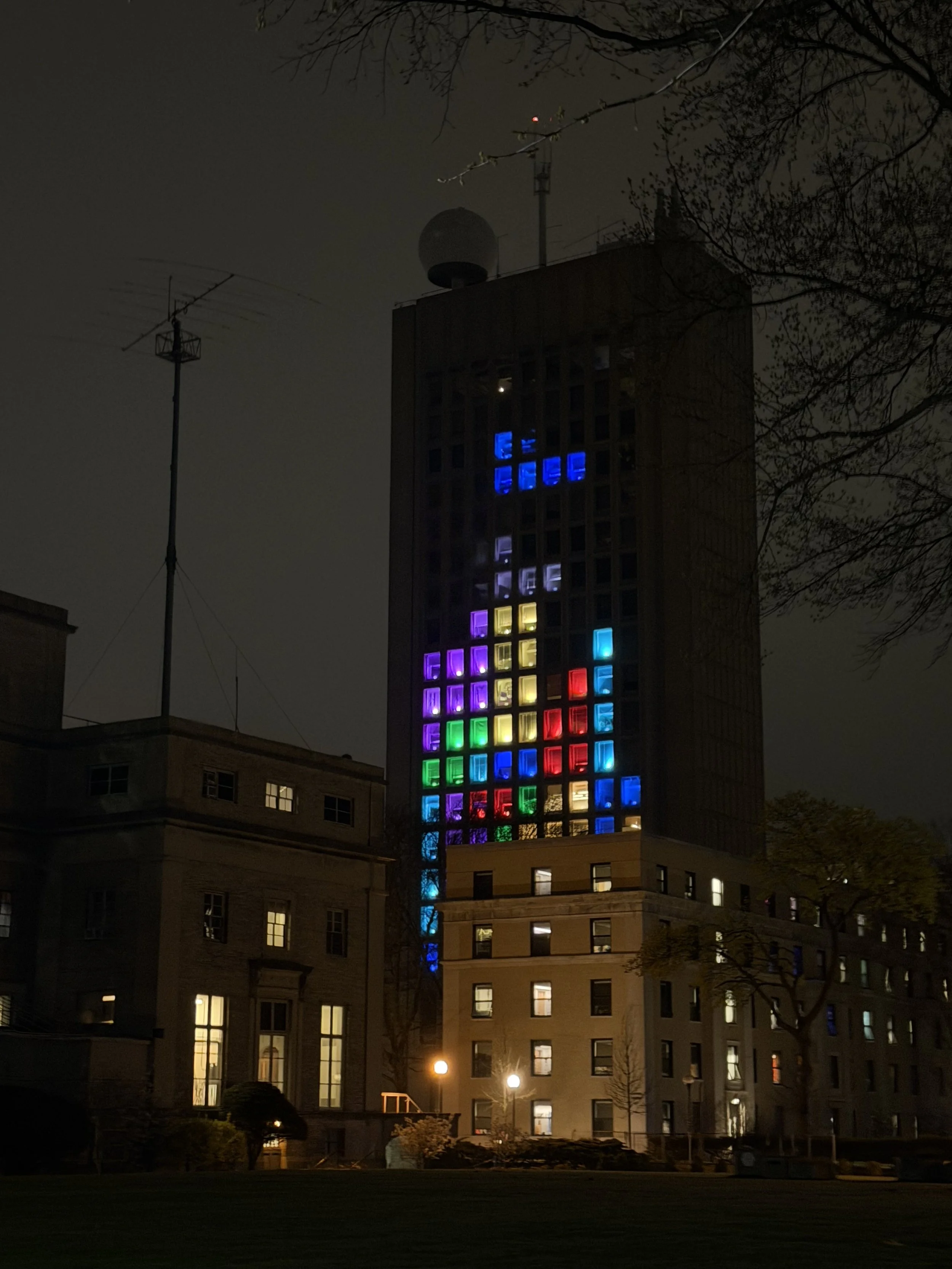
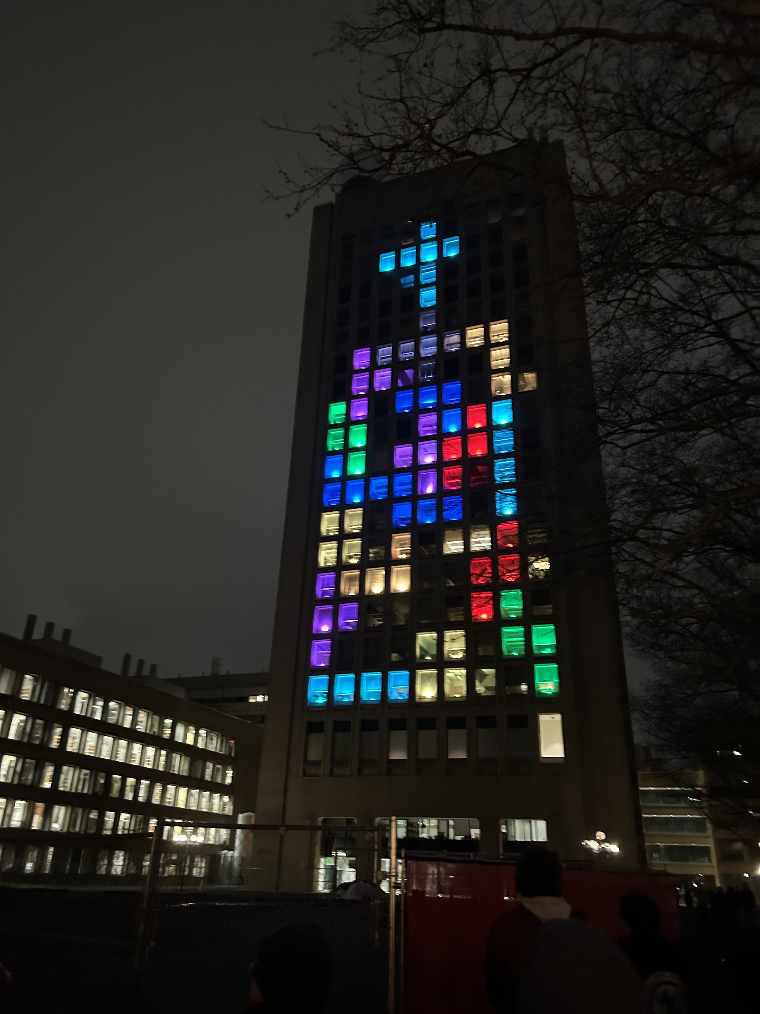
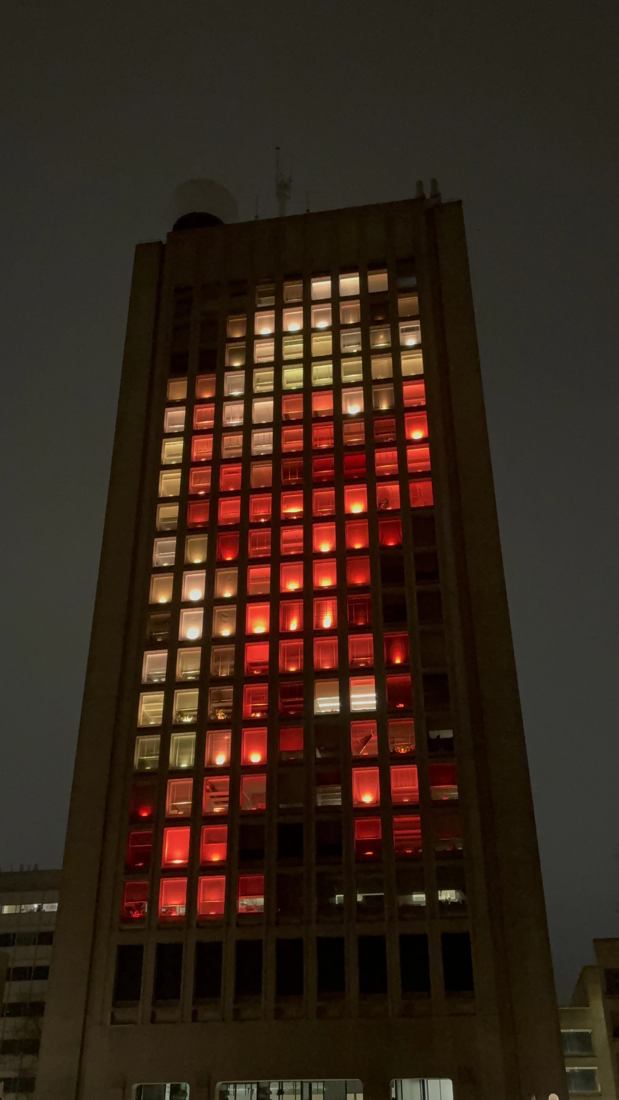
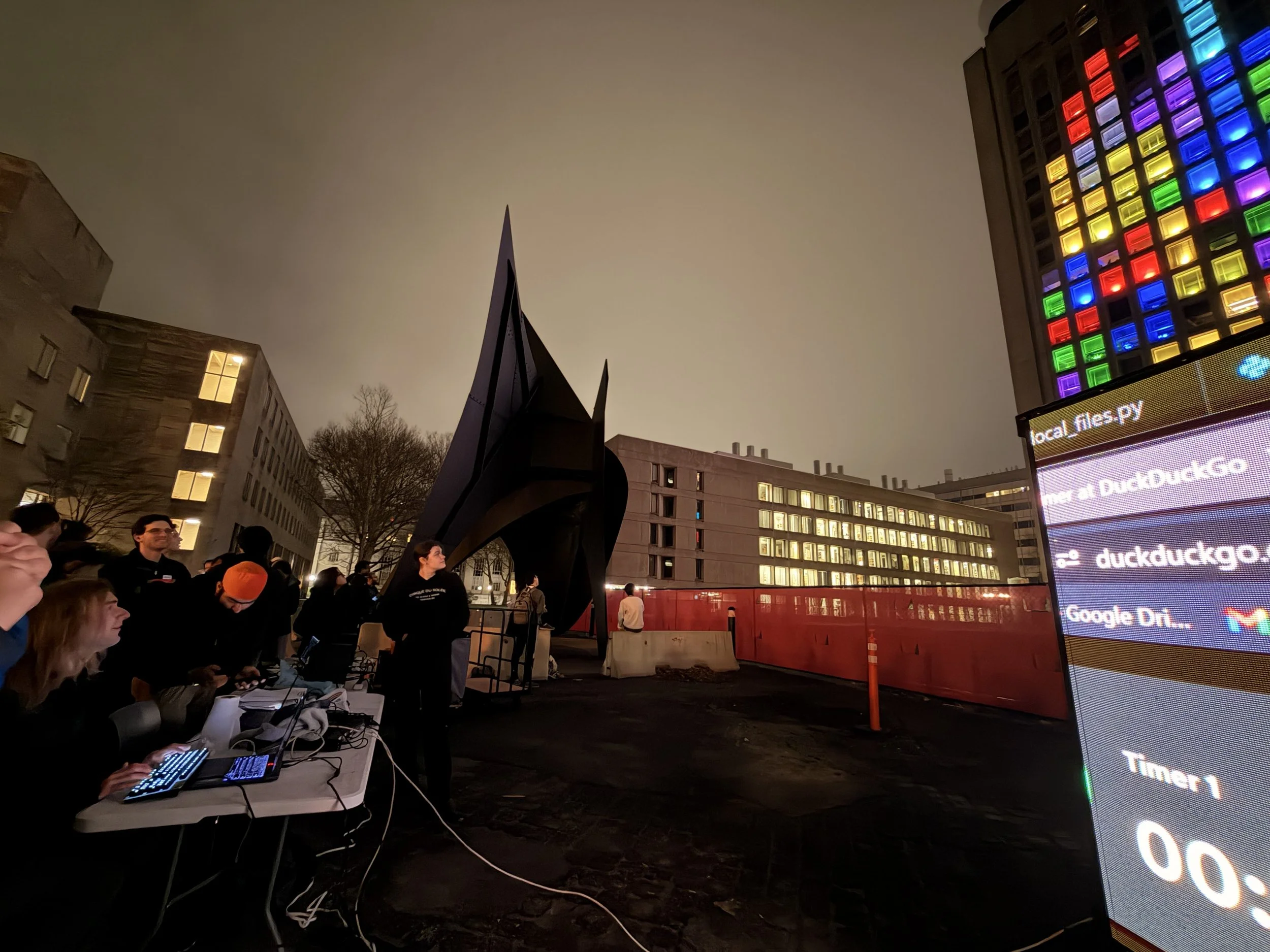
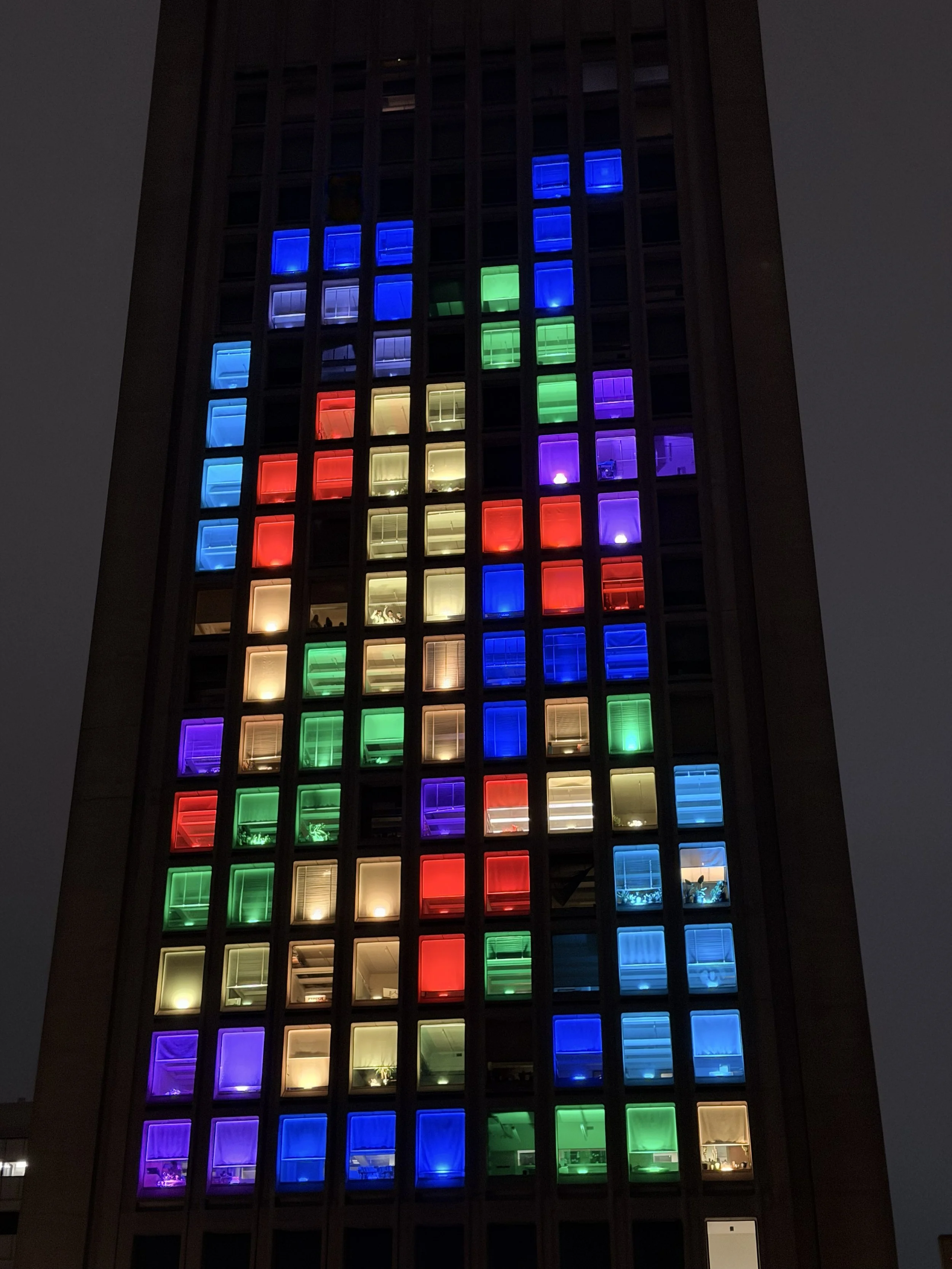
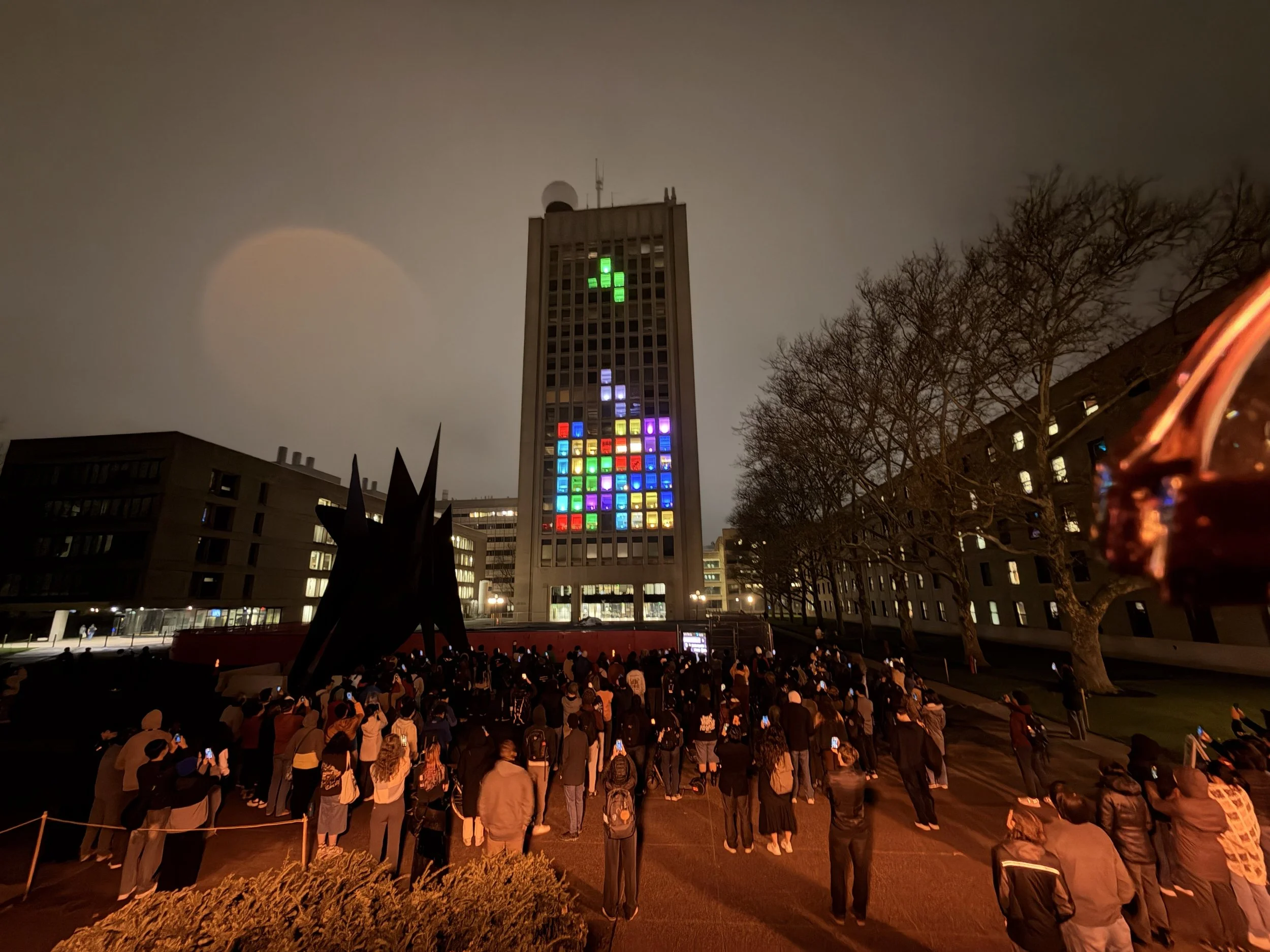
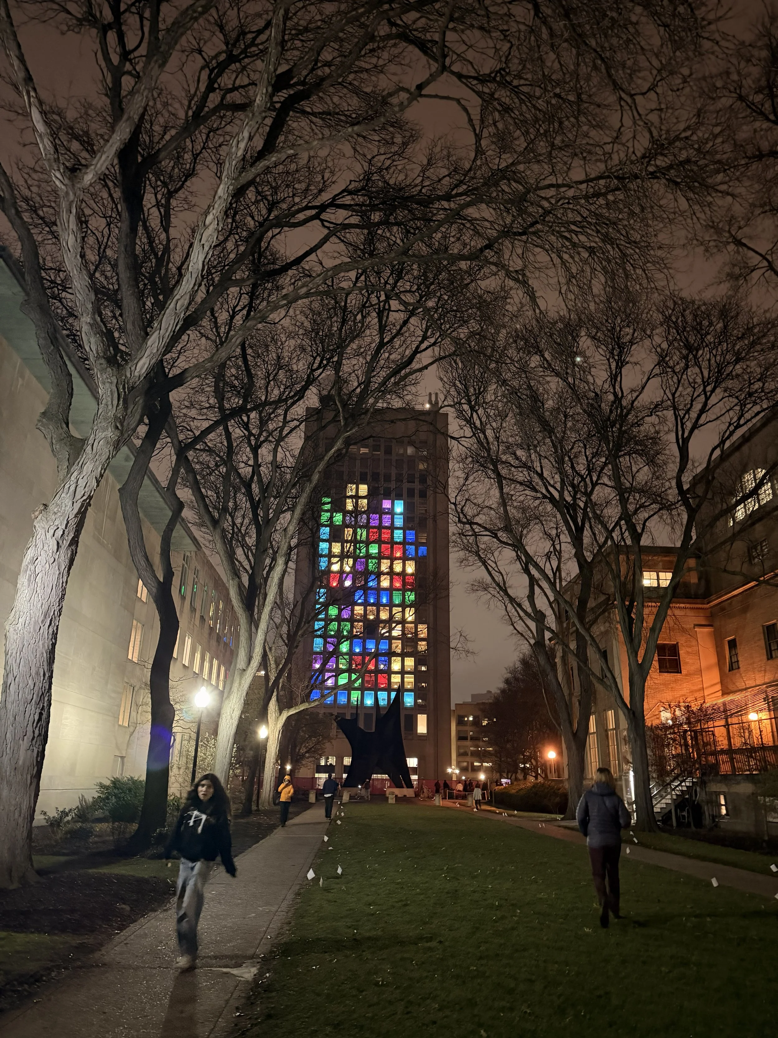
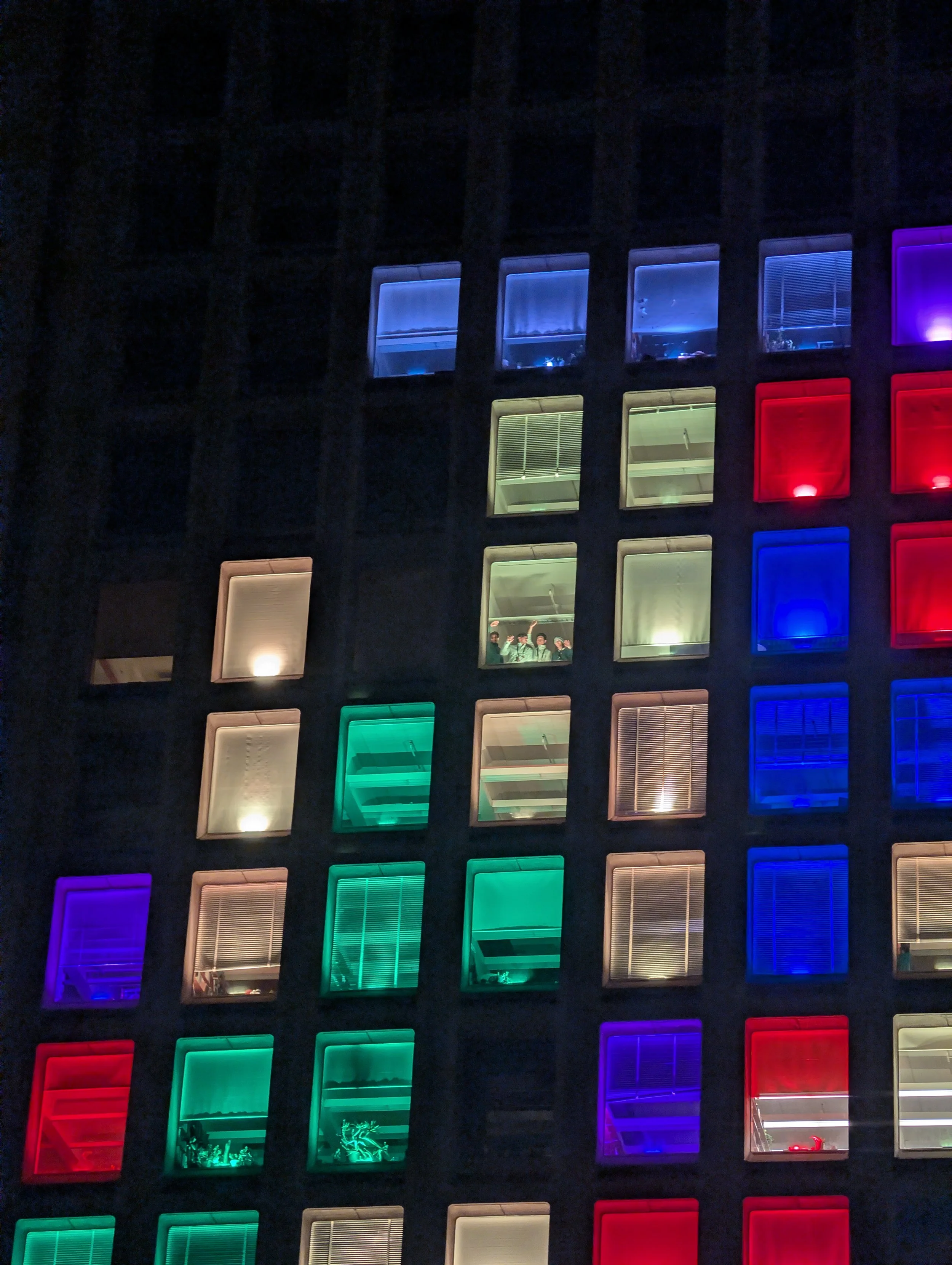
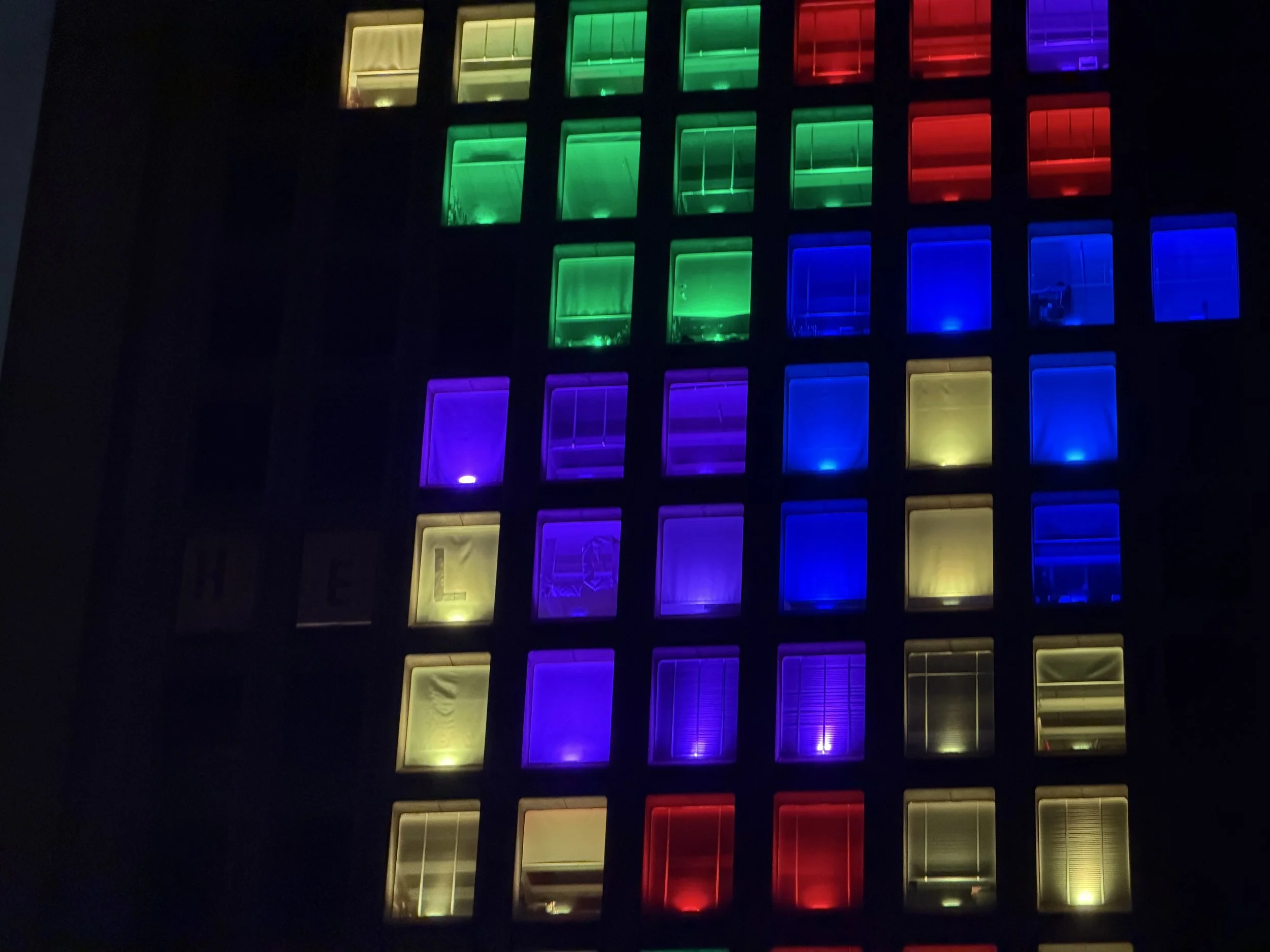
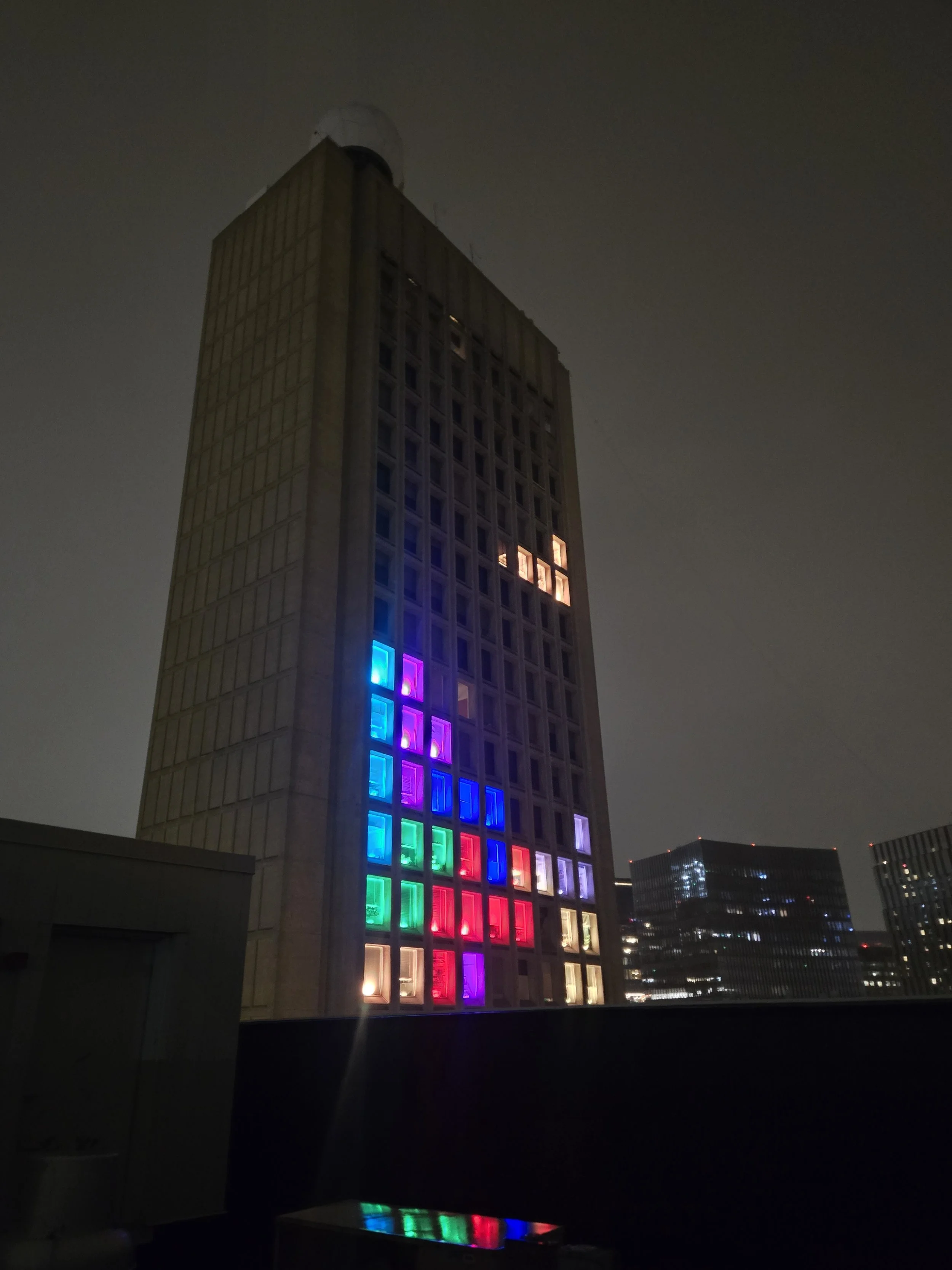
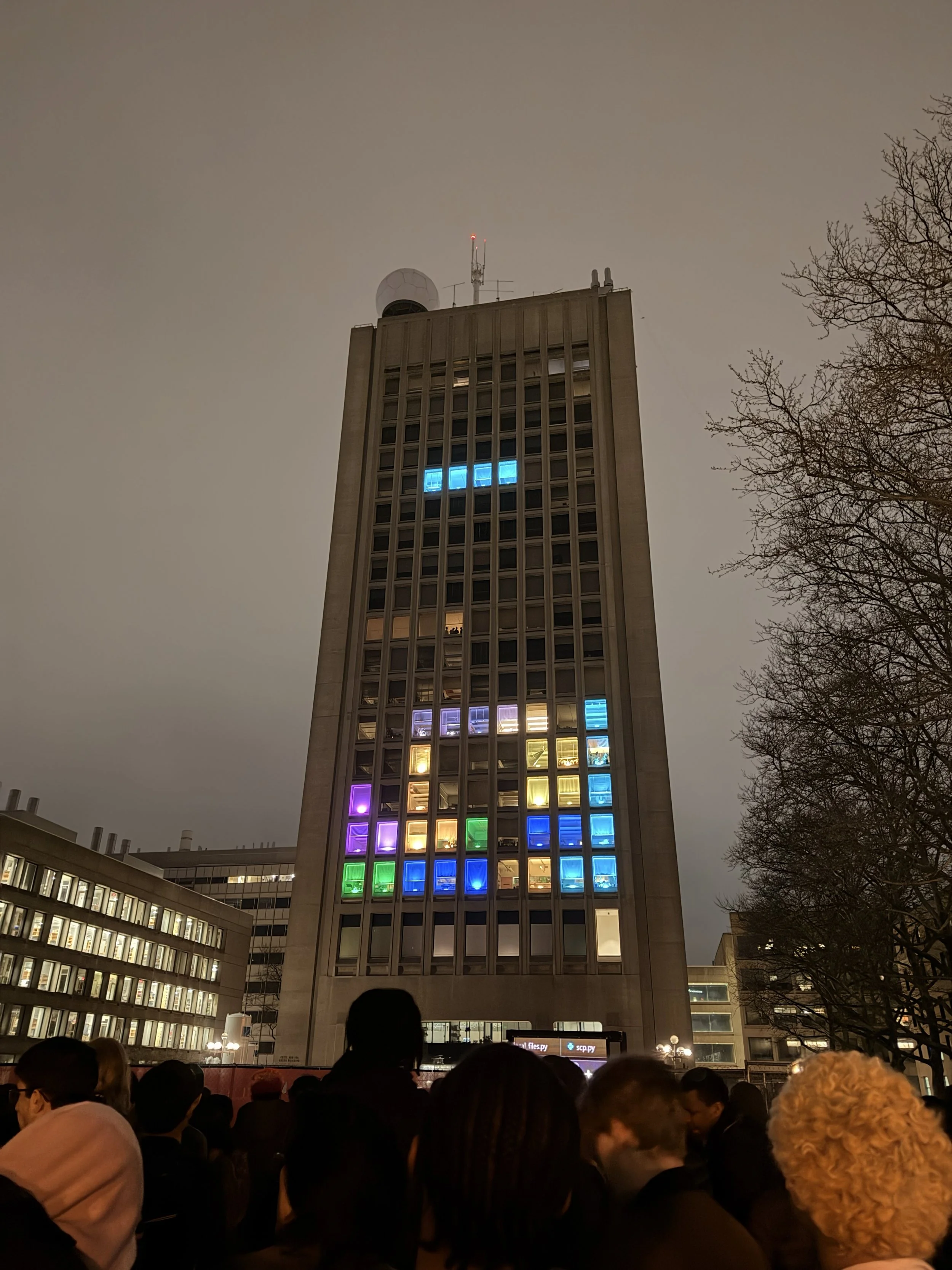
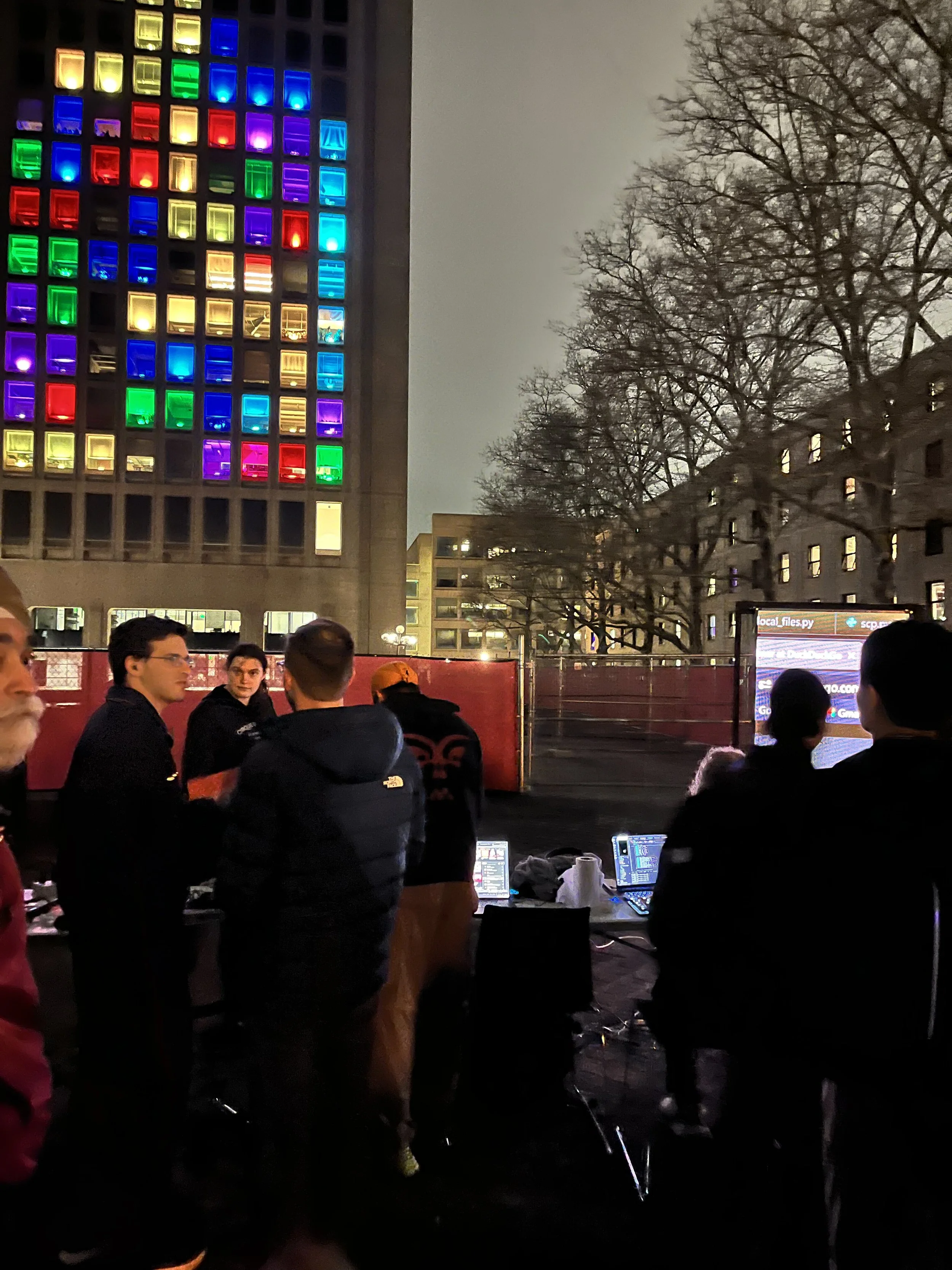
Finally, after 3.5 months of development, and two extremely intense weeks of building and deploying hardware, we had the entire display ready for use. Our CPW reveal event was attended by hundreds of people, and we played Tetris for almost 5 hours straight. Here are some photos and videos:
Ongoing Maintenance (April – May 2026):
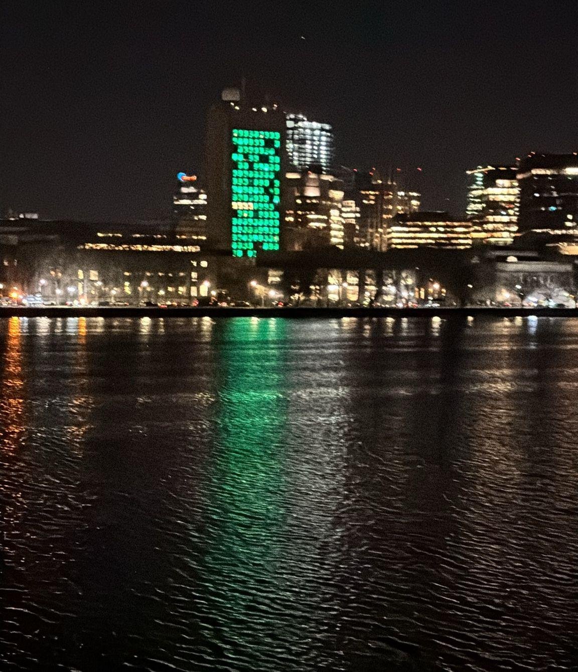
A view from across the river of windows that struggled to authenticate
Although the installation was fully functional for the CPW reveal, it quickly started to develop issues. Even during the reveal event, some of the module took dozens of tries to authenticate and we had to use a handheld Yagi antenna pointed directly at the modules to be able to receive a response from them. As with any large sample size, there was a distribution in the performance of the radios within our Tetris modules. Due to random variations in the fabrication of the components, some modules would work well, authenticating reliably with minimal retries, while others took numerous repeated attempts, and some even stopped replying.
We initially tried to fix this by adding a second LNA on the receive side of the base station, and adjusting the antenna type and orientation, but this had almost no effect indicating that the issue was poor signal to noise ratio of the modules transmitting against the background noise. We attempted to raise the transmit power of the spare modules we had from +17 to +20 dBm, but found that it often ended up killing the microcontrollers when they tried to transmit.
One of the potential causes of this was that the linear regulators we used for CPW were technically operating outside of their recommended range during the short transmit pulse. So I upgraded them with a proper bodge board.
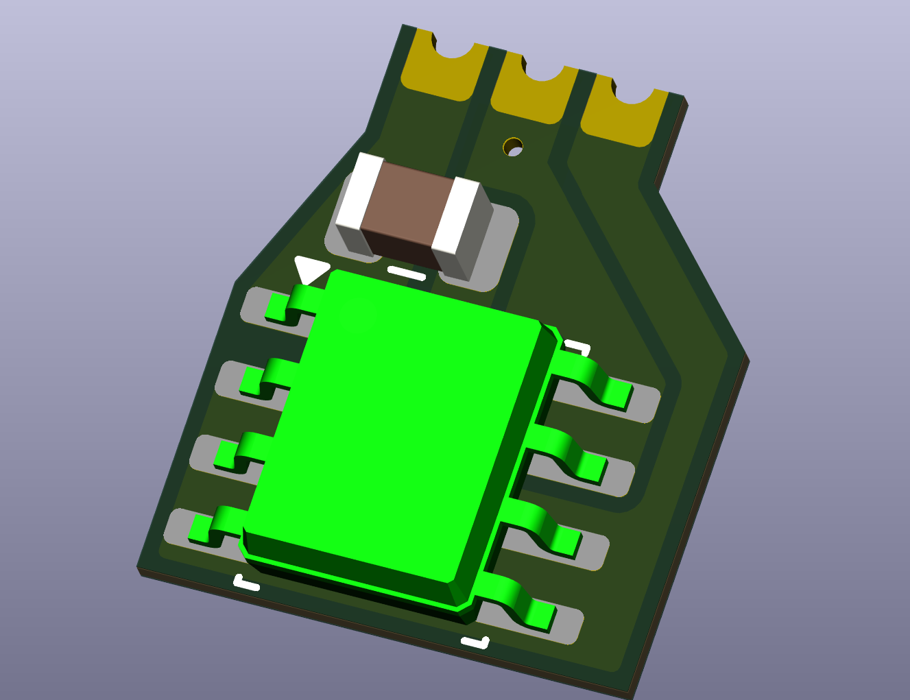
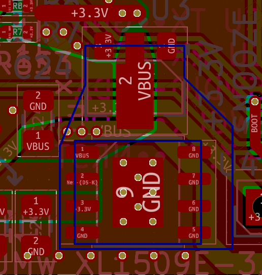
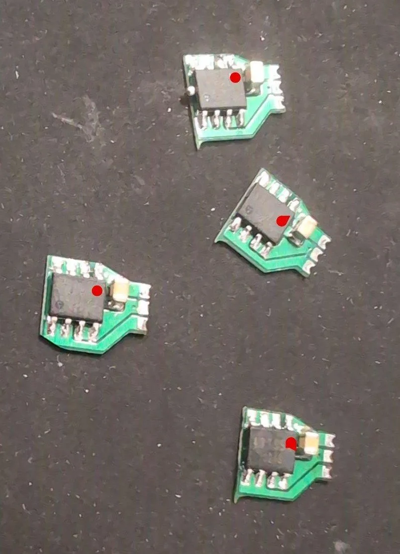
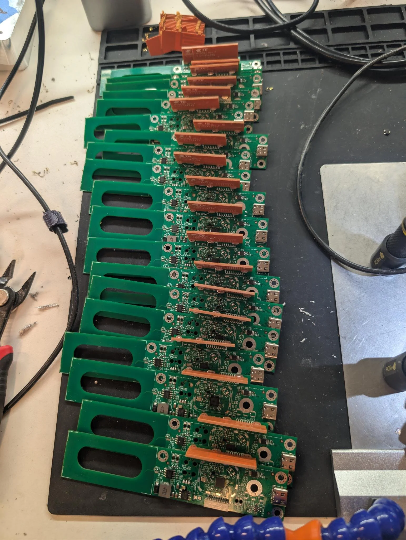
The finished fleet of revised boards with bodges and PCB antennas
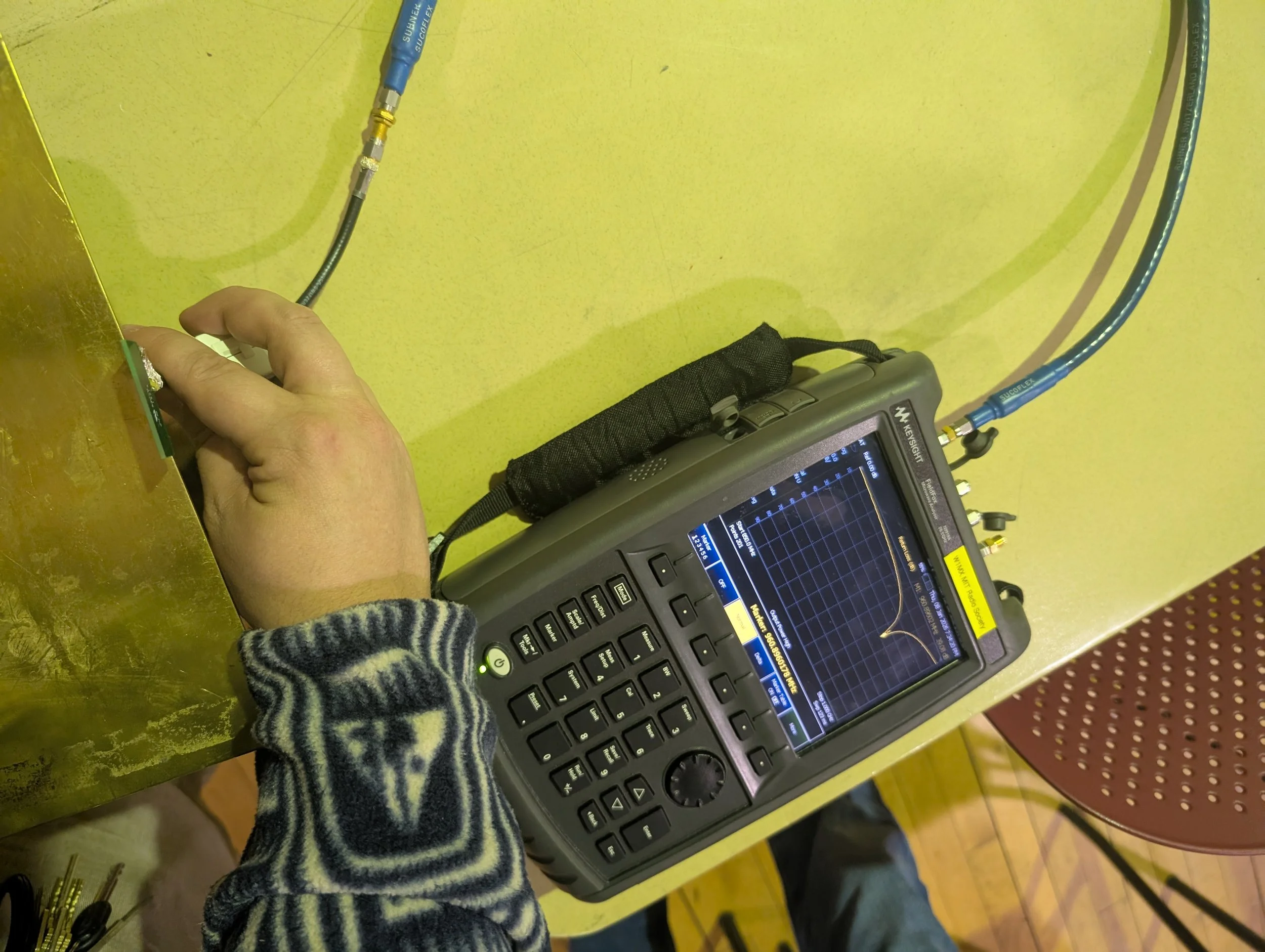
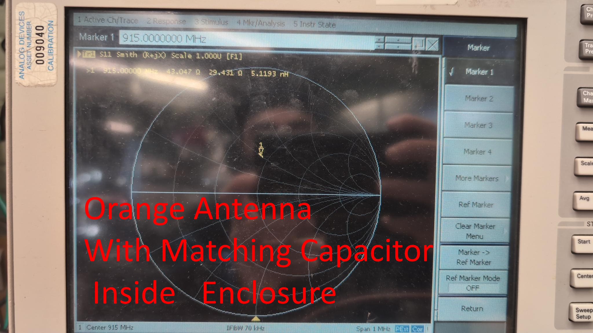
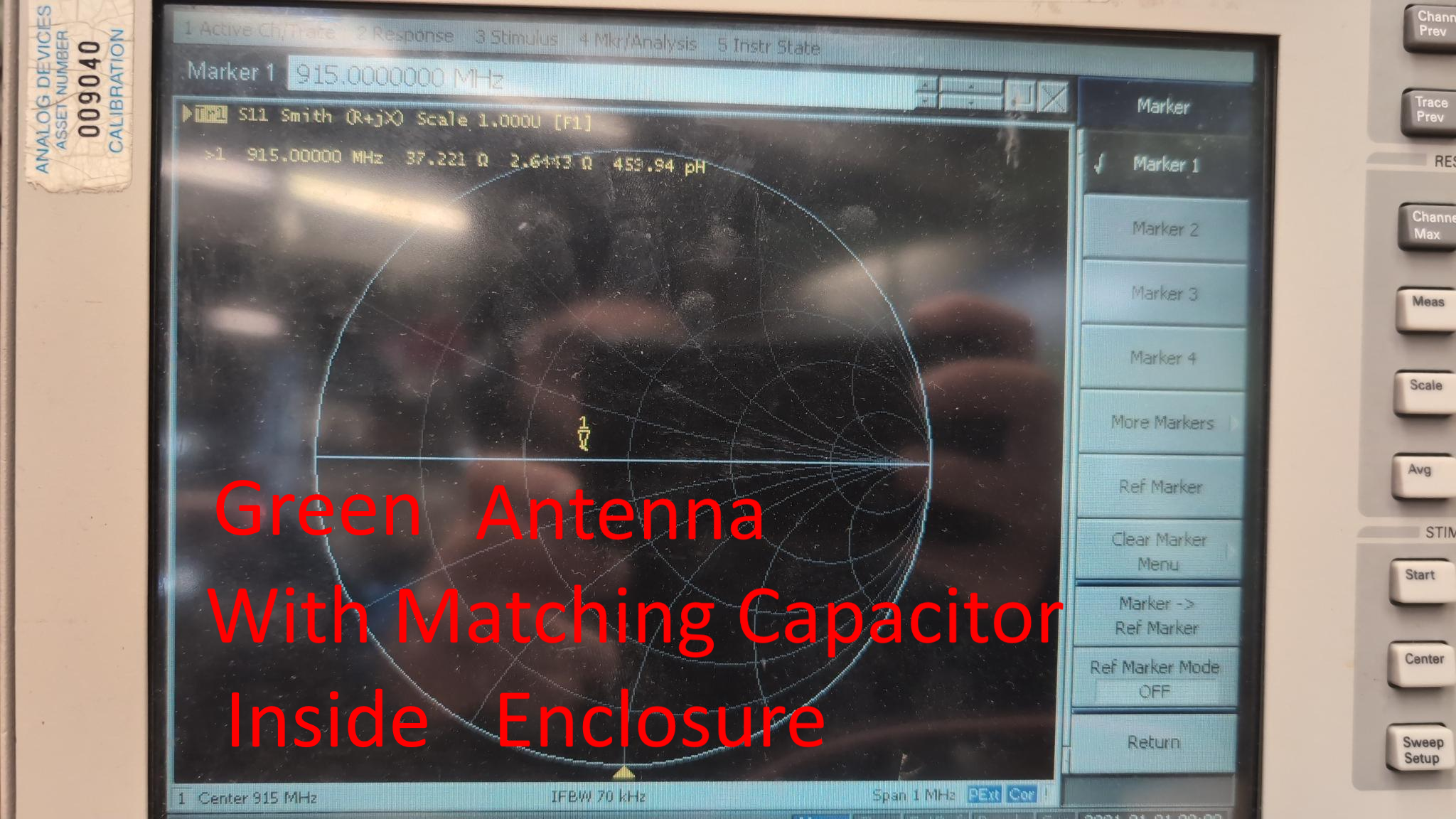
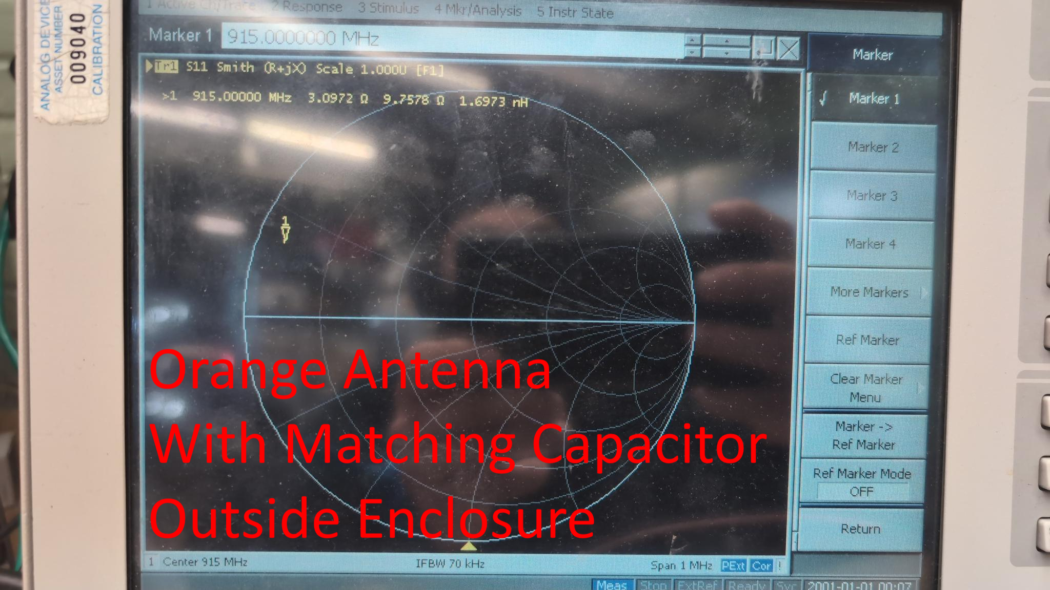
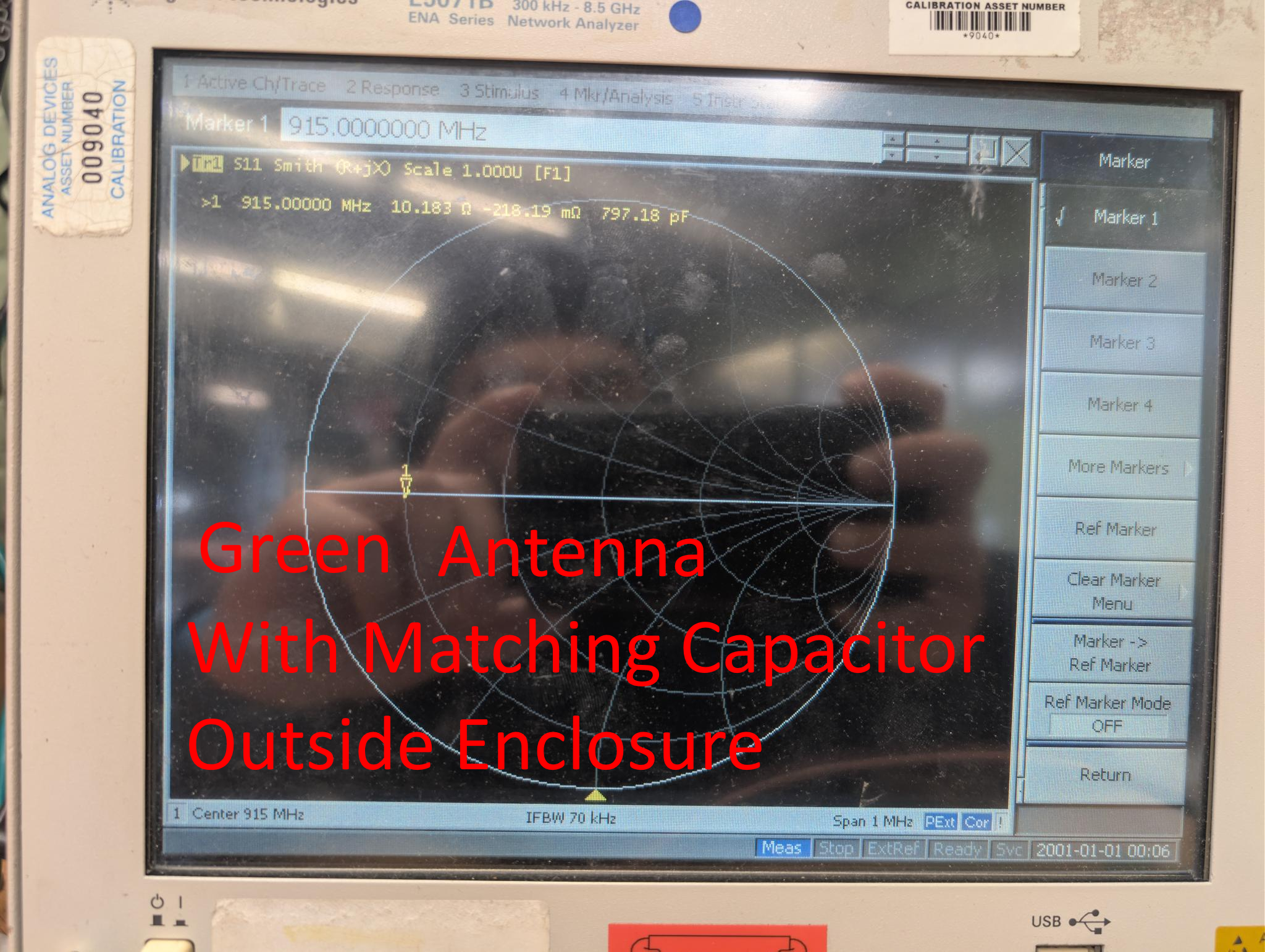
This didn’t resolve the issue completely, so to investigate further I took the modules to the MIT Radio Society workshop where I discovered that although the spiral antenna worked slightly better than the PCB antenna when just used as a drop in replacement, with the addition of a small shunt capacitor the PCB antenna could be better matched to the microcontroller, meaning more power could be transferred to the antenna, and less would be reflected back into the microcontroller (reducing the chances they die).
So I bought the PCB antennas and capacitors and built more spare modules up with these changes and swapped them into the building until we had a fully functional fleet.
Conclusion:
This was the most ambitious and largest scale hardware project I have ever undertaken, and there is no way I could have done it alone. I learned a lot about the challenges and issues that crop up with large quantities, and how to resolve issues that arise even after boards have been fabricated and another revision cannot be made. I am very grateful for all the other students that contributed to the development and mass production of this project.
If you are a maintainer of the Tetris project, please access this page using the Tetris password to receive files and instructions to help you test + fix issues with the hardware / software.