JARVIS JET ENGINE:
JARVIS initially began as a 1-month sprint to assess whether AI tools such as Claude and ChatGPT could significantly accelerate hardware engineering work. The idea was to give teams of students access to all the big AI models as well as industry standard CAD and turbomachinery software to see if they could design, build and test a jet engine all within MIT’s independent activities period (4 weeks in January of each year).
Designing a jet engine is an extremely intricate and interconnected engineering problem. Each part influences every other part in the system, and because the temperatures and rotational speeds are so high, you run very close to the limits of what most materials are capable of. The central issue arises from the fact that a full thermodynamic cycle takes place simultaneously across the entire system. The compressor must draw in cold air and squeeze it into the combustor at a higher pressure. Fuel is burned in the combustor, heating the air to make it expand. The expanding air is forced through the turbine which must harness enough power from the air leaving the engine to run the compressor, since they are linked together on a single shaft. This circular dependency makes engine design a careful balancing act between how much the air can be compressed vs how much power can be extracted at the turbine and the efficiency losses at each stage. On top of this one must worry about the spinning assembly vibrating itself apart, the compressor and turbine expanding radially under centrifugal force, how to pass lubricating oil through all the bearings and a dozen other competing influences not to mention the final thrust produced and weight of the entire system, which were the metrics we were scored on.
My team consisted of (left to right):
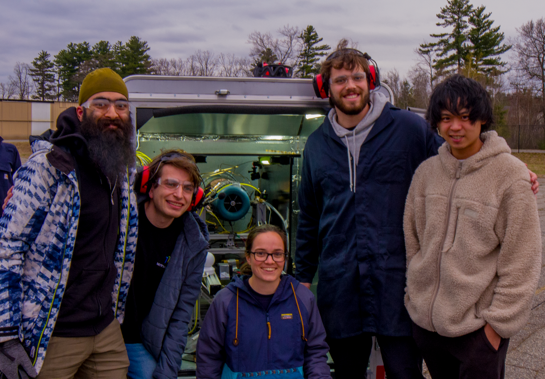
Anhad Sawhney (senior in Electrical Engineering) - Turbine design, control system design, finite element analysis, machining, test readiness
Yaakov Zerykier (senior in Mechanical Engineering) - Rotodynamic analysis, finite element analysis, machining, sourcing/supplier negotiation
Elizabeth Tupaj (senior in AeroAstro) - Subscale & full scale combustor design
Zachary Bleil (senior in AeroAstro) - Rotodynamic analysis, compressor design, sourcing/supplier negotiation
Ethan Wong (junior in AeroAstro) - Thermodynamic cycle design, compressor design, nozzle design, machining
This team had completed the most amount of relevant coursework by far, and we also had a generous amount of hands-on experience through personal projects and internships. Due to this, we used the AI’s the least. Ultimately, the program ended up taking until mid-April, mostly due to the suppliers doing the metal 3d printing / CNC machining of our components having a slow turnaround time. Even still, out of six teams of 4-5 people each, my team was the only one to successfully generate thrust with a working engine at the end of the semester.
Final Result:
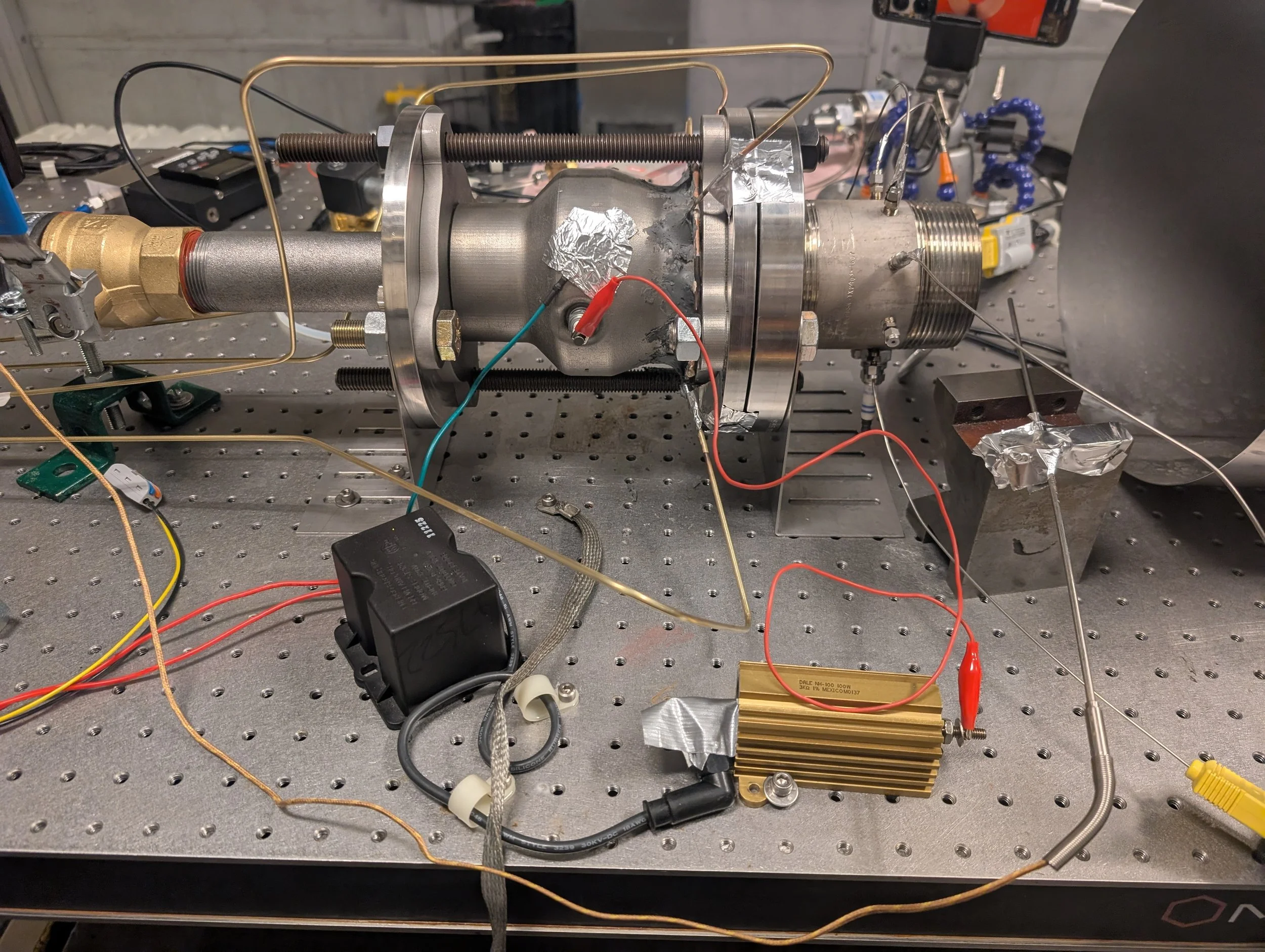
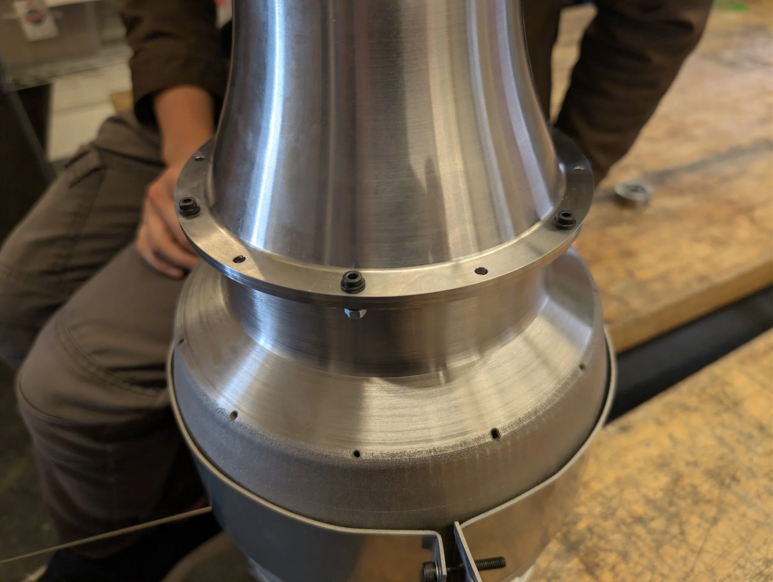
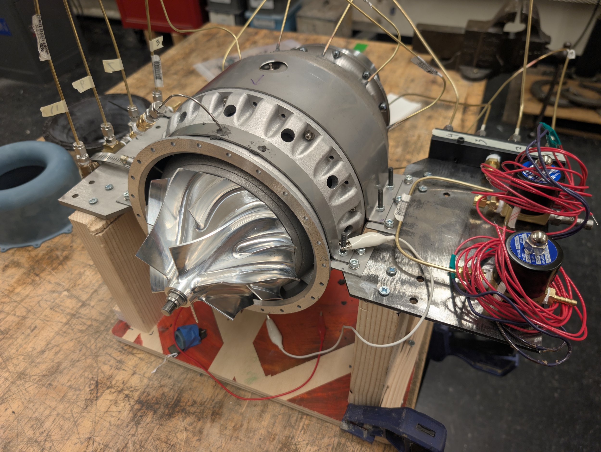
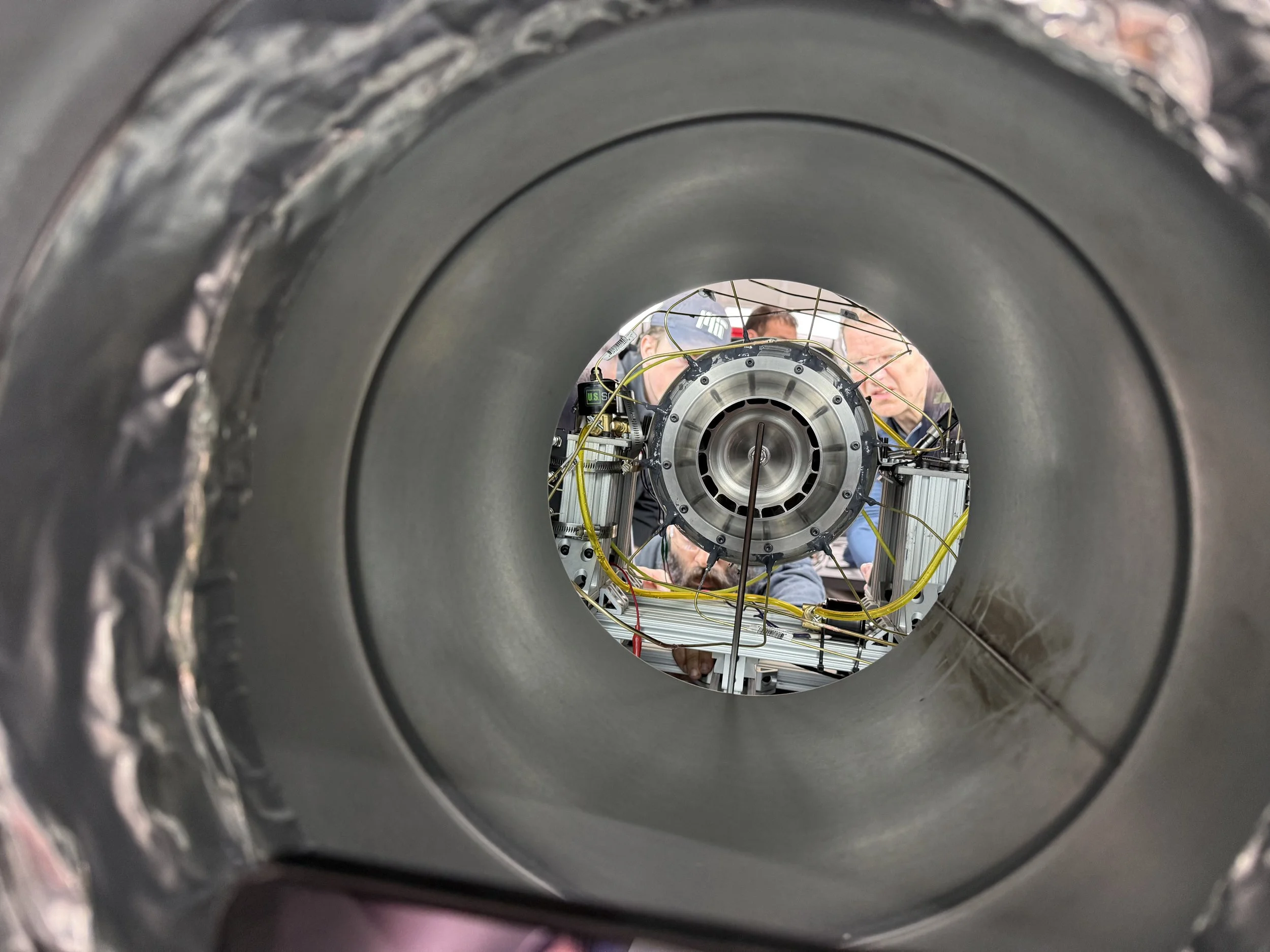
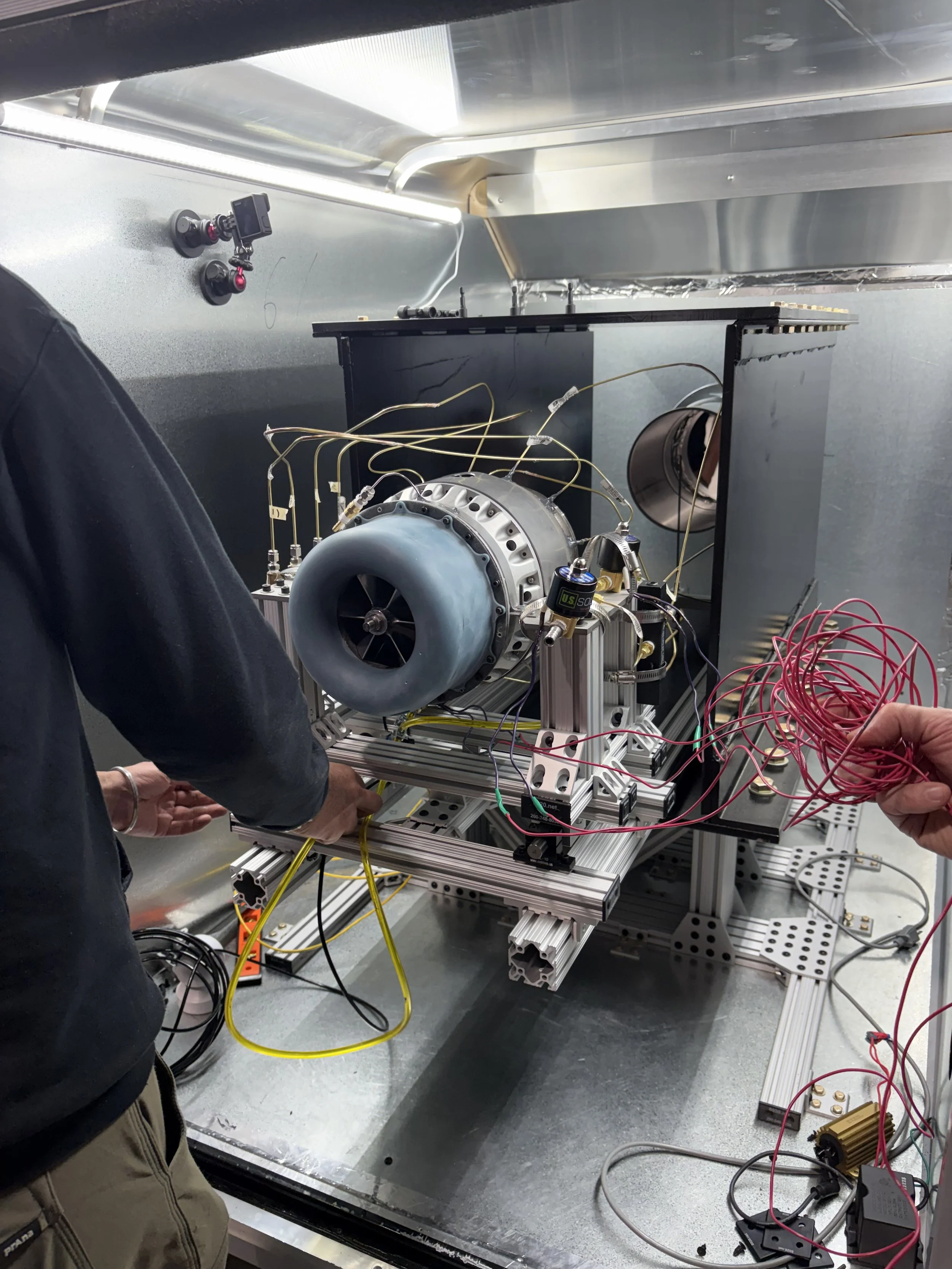
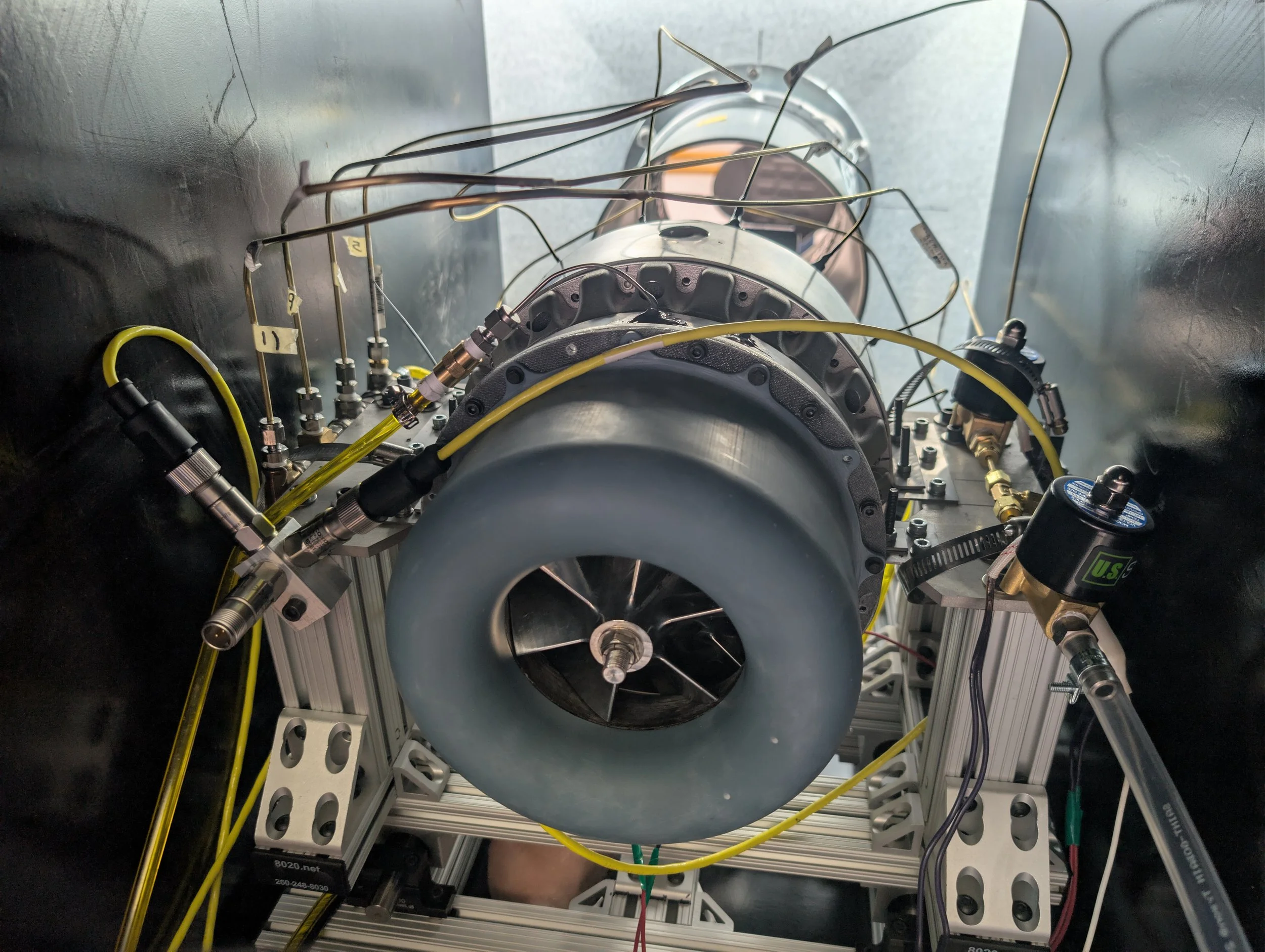
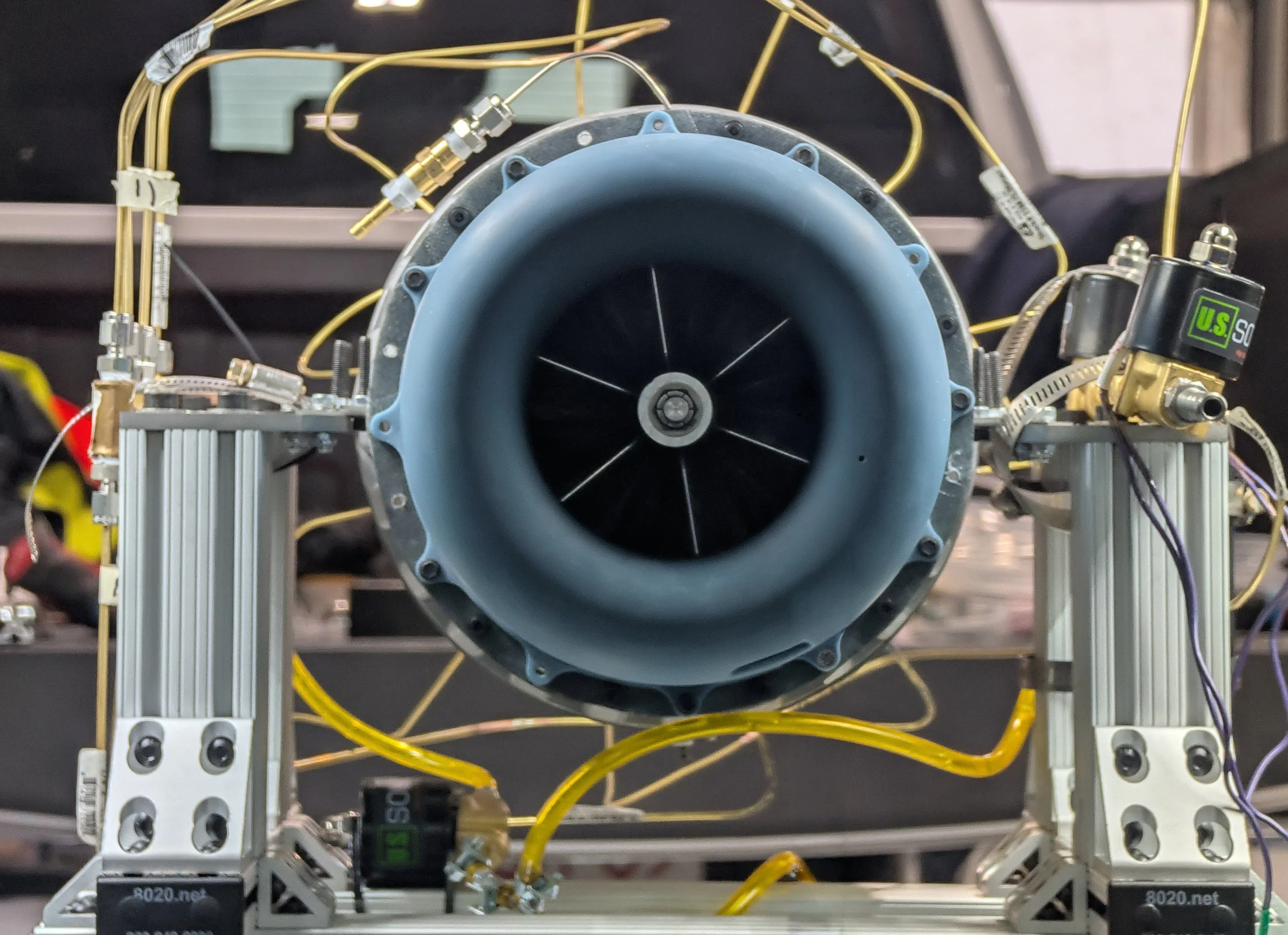
We built a single spool micro turbojet engine with a single stage mixed-flow compressor, annular monolithic combustor, and single-stage turbine.
Below is a picture of our finished engine and its CAD model, as well as our final presentation. For videos and test results, please scroll to the bottom of the page (the whole process is catalogued in chronological order):
The story:
JARVIS was initially posed as an IAP program. IAP (Independent Activities Period) is MIT’s special January term where there aren’t traditional classes. Instead, there are several events (such as MIT mystery hunt and the integration bee), short classes that aren’t strictly related to a major such as glassblowing, and special programs such as JARVIS. The fact that this program took place in IAP meant that the students participating would not have any other significant demands on their time (such as coursework or team sports). Everyone on my team was able to dedicate practically their entire day to engine work for these 4 weeks.
JARVIS started with 6 teams of 3-5 people each. My team was called “811 crew” since the three AeroAstro majors on our team had all taken 16.811 (Advanced Manufacturing for Aerospace Engineers, a class that teaches metal 3d printed impeller design) together. This gave us an advantage because those three had done coursework involving software packages similar to the ones we were given to carry out our design. They had also taken other classes that teach about thermodynamics with a specific focus on jet engines as part of their major.
Program Structure:
All the teams underwent a design review at the end of each week in January. To the right are our slideshows from each of these Friday design reviews, with some redundant slides removed. The design reviews were carried out by Zachary Cordero and Zoltan A. Spakovsky (two professors in AeroAstro whose research and classes focus on turbomachinery) plus some grad students under them. The program was also sponsored by Safran (a French jet engine company), Beehive (an American jet engine startup), and Boom Supersonic (an American supersonic plane startup). Representatives from those companies attended our design reviews as well. If at any of these reviews the course staff felt we were unprepared to take our engine to the next phase of development, our team could be cut from the competition. By the end of January, the only other team to be given permission to manufacture their engine alongside my team was a team called “Fast and Fractured” composed of 4 seniors in mechanical engineering who were also all members of MIT motorsports. (They had the second most amount of relevant coursework and practical experience).
Five other teams got cut over the course of the month because they got misled by the AI and lacked the coursework and experience to correct it, could not hit key design milestones in time, or dropped out of their own accord.
The original intent was for the entire process of design, fabrication and testing for each of our engines to be completed within the month. Alongside our full engine design, we also had to make a subscale combustor that would burn fuel in a test rig and demonstrate that our full scale engine was safe to run. The course staff were very optimistic that AI tools would immensely accelerate our work, but once things got underway it became clear that at best only the design could be completed after 4 weeks. Additionally, suppliers ended up taking several weeks to 3D print or machine our components so the final testing dates got pushed towards the end of the spring semester.
Software and other resources:
We were each given $300 credit to spend with any of the major models (ChatGPT, Claude, Gemini, etc.) through MIT’s internal LLM wrapper Parley. We were also given access to SolidWorks for CAD, ARMD for Rotodynamic simulation, and Concepts NREC AXCENT / AXIAL / COMPAL for turbomachinery simulation and design. Additionally, many students at MIT have access to various Ansys simulation packages (Yaakov from our team had it since he was on the solar car team and the motorsports students also have it).
Alongside the software packages we were given the full lecture slides from 16.811 and a textbook on gas turbine design. We could look up anything on the internet and ask the AI anything we liked, but we were not allowed to consult any people outside our team for assistance or guidance.
At the end of each day each student had to submit a questionnaire on how the AI helped / hindered us, and at the end of the week we had to prepare a summary of the team’s AI usage.
INITIAL CONCEPTUALIZATION (January Week 1):
We began our process by designing the thermodynamic cycle which would take place within our engine, settling on the key parameters including how much the air would be compressed before combustion, the exhaust gas temperature (EGT), the rate of mass flow through our engine, the amount of thrust we were targeting, etc. The numbers we settled on are in the slides. Ethan had written his own software tool that used a genetic algorithm to reconcile the competing influences and settle on a cycle that would work.
Once we had these operating points, we could go about designing a compressor and turbine that would hit the desired pressure ratio, harvest enough energy to power each other, and do so at the maximum efficiency achievable.
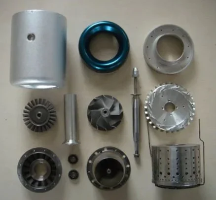
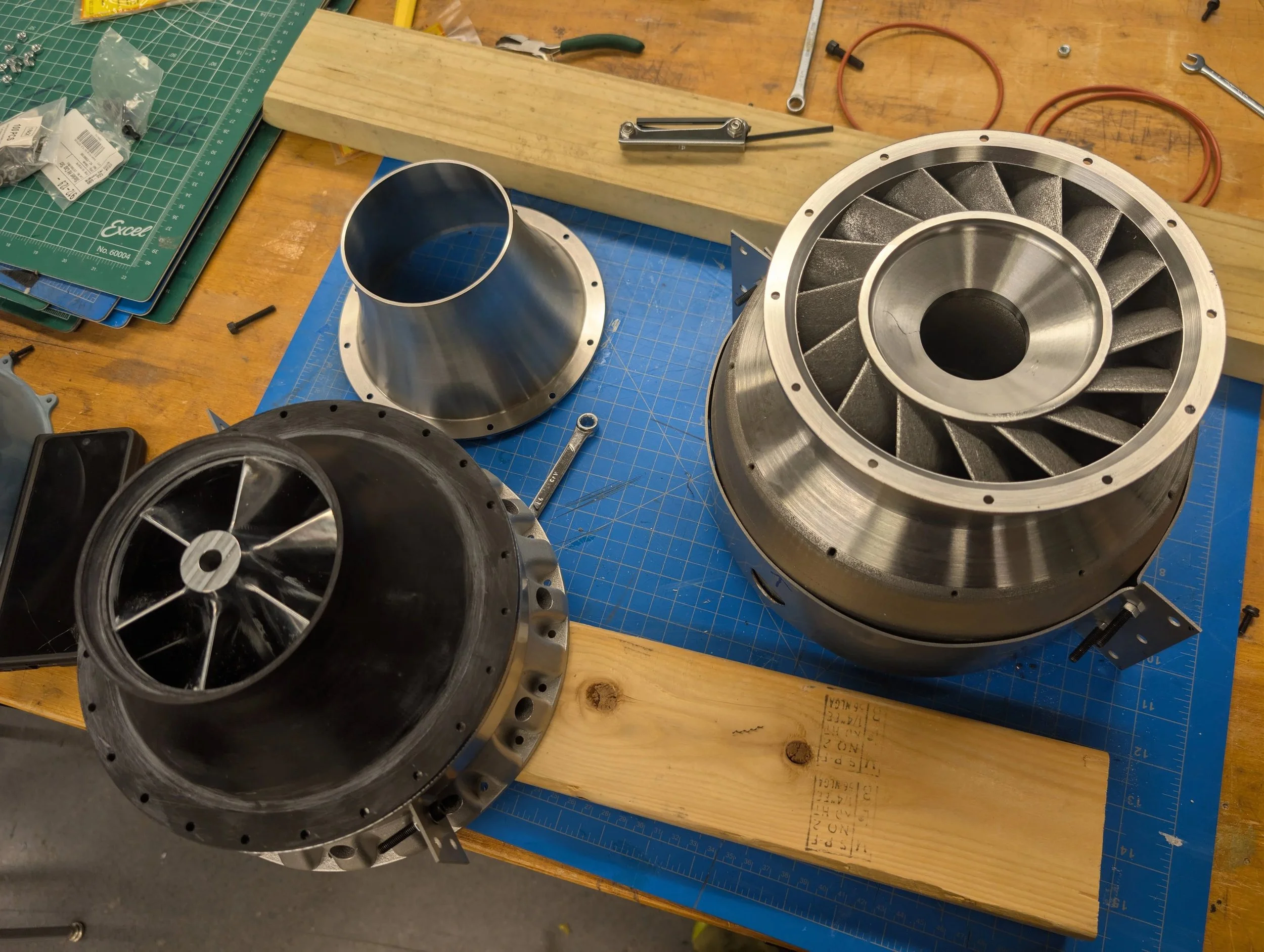
The parts of a JetJoe Engine
In the kickoff meeting, we were given a commercial off the shelf JetJoe engine to disassemble and inspect to see how an engine of similar size solved the engineering problems we would encounter. So, our preliminary design was quite similar to the JetJoe with a radial compressor that ejected its air as a thin tube around the outside of the engine through two sets of diffuser vanes.
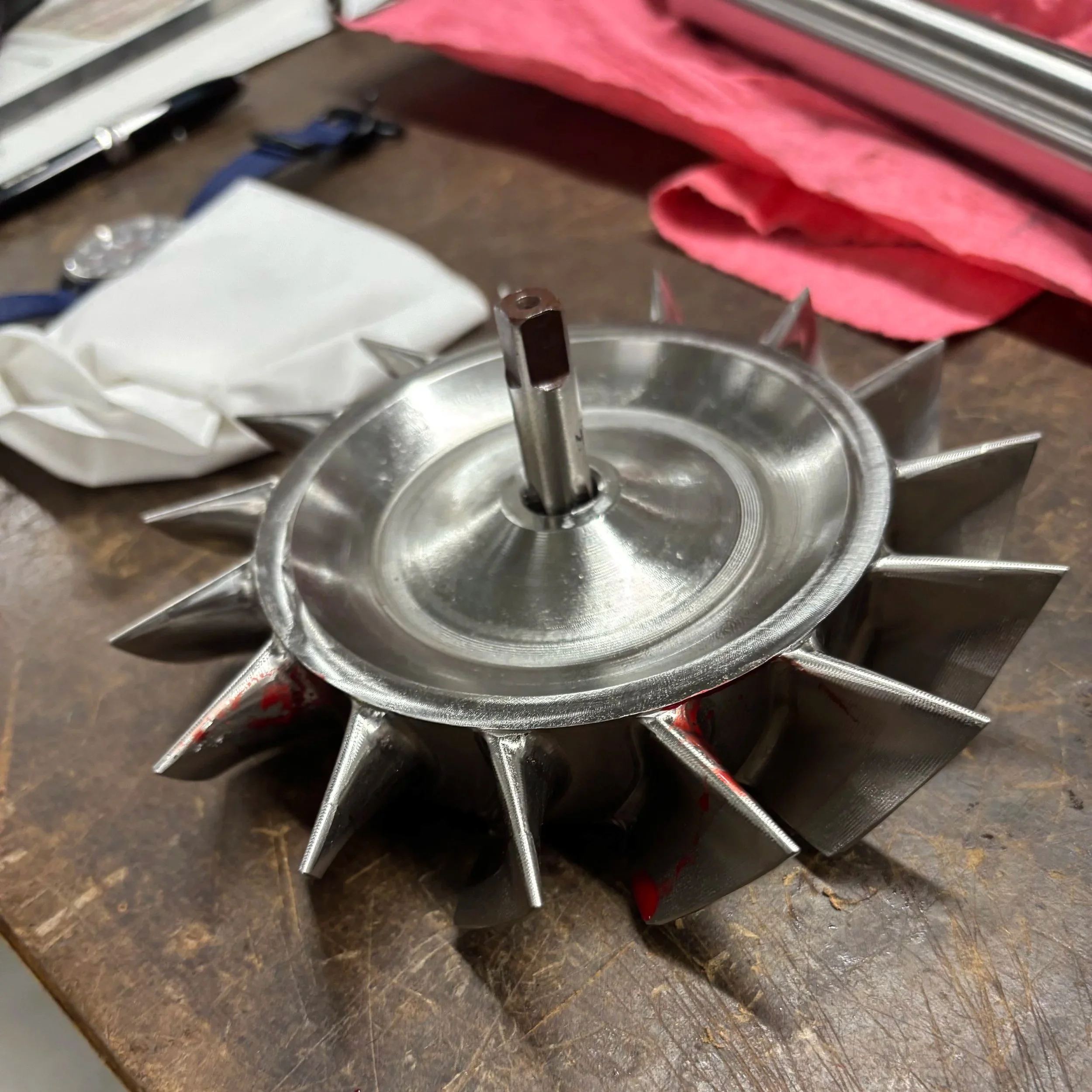
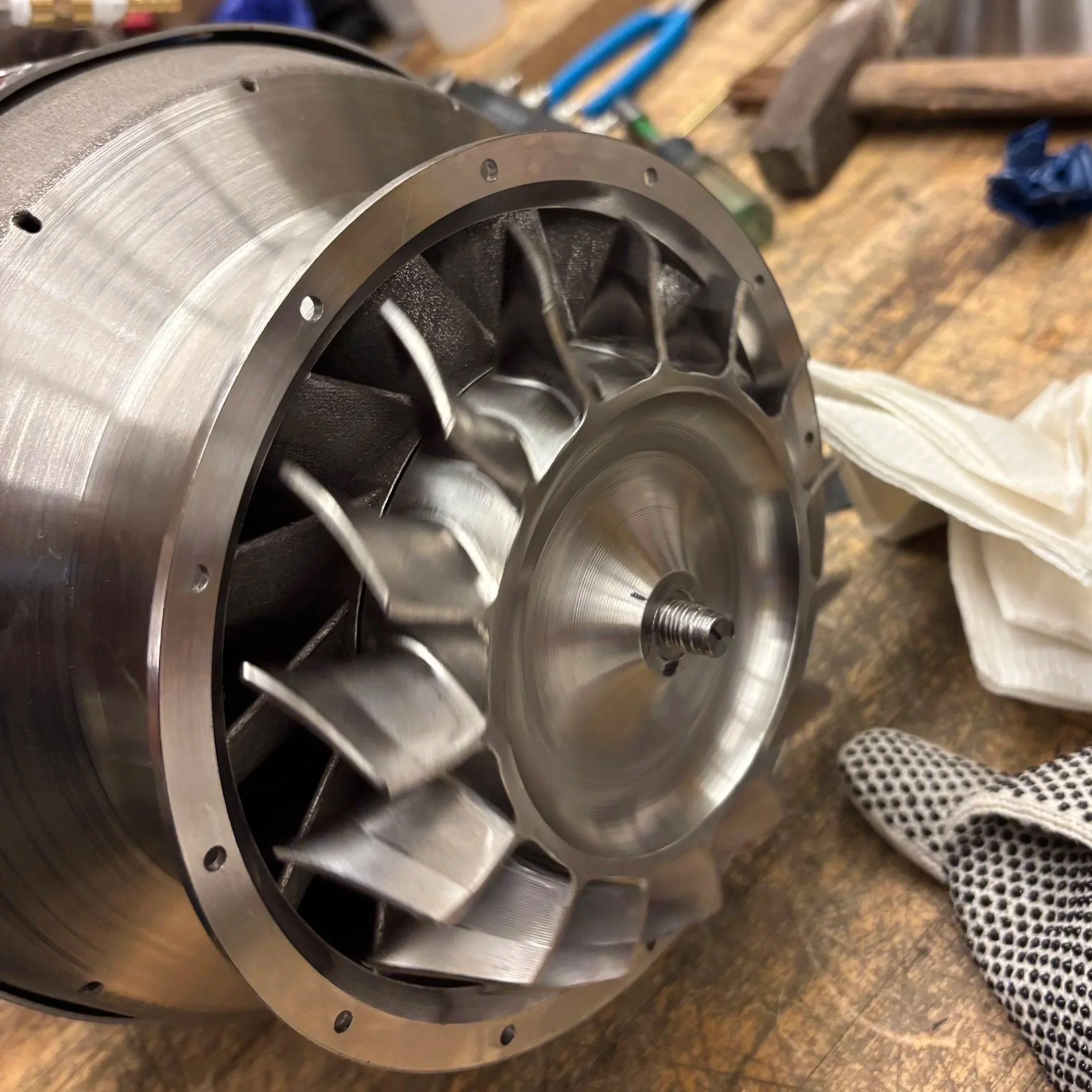
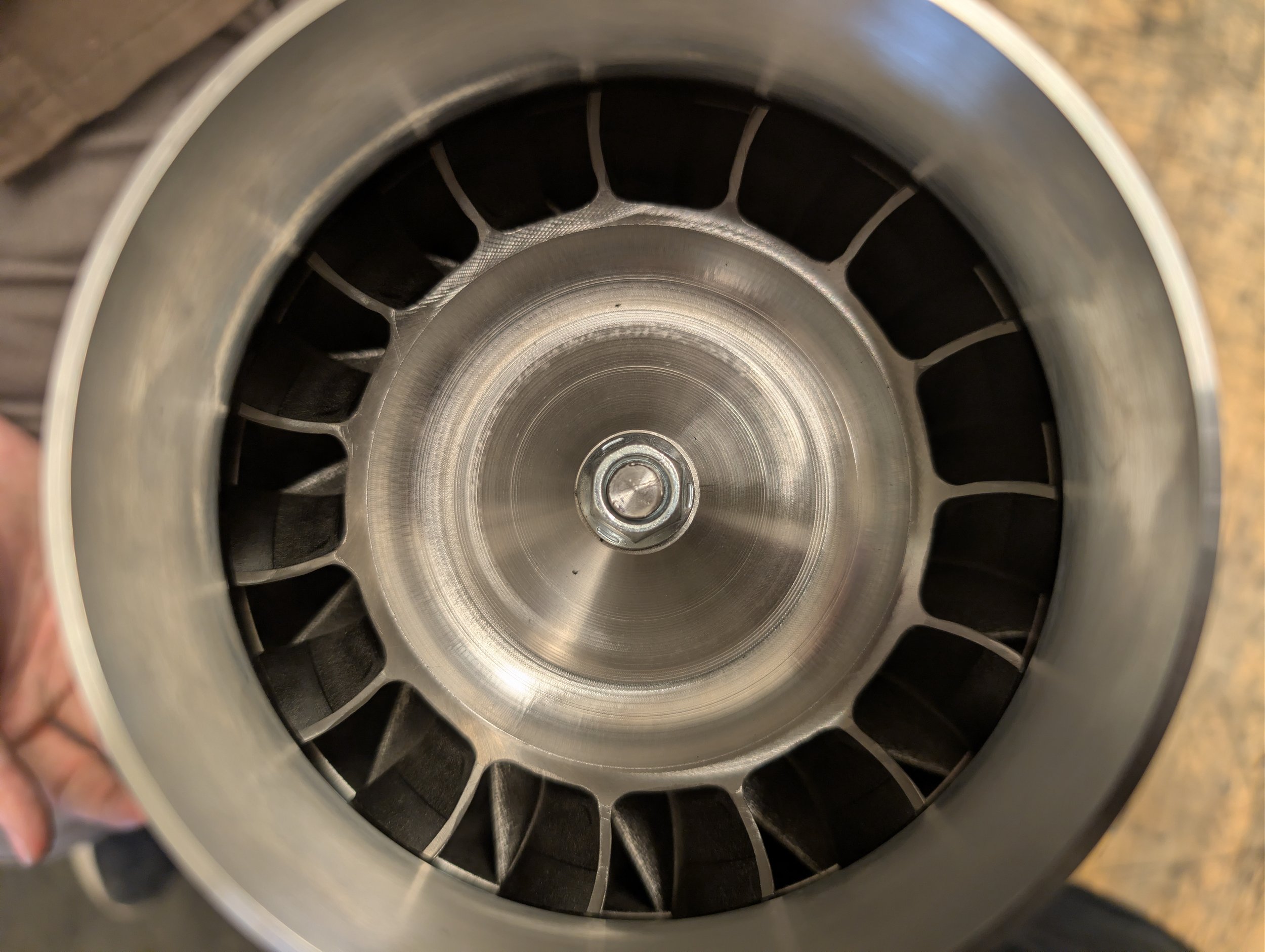
During this week, I took on the turbine design while Ethan took on the compressor. We iterated through designs using AXIAL, tweaking blade geometry and running CFD simulations to monitor the airflow through our blades and ensure they were hitting the numbers we needed. Every so often we would export the blade geometry from AXIAL and bring it into Solidworks FEA to assess whether the desired shape would fracture under the centrifugal stress of spinning at over 40k RPM and (for the turbine) being heated to 1100K.
On the turbine side, one of the major struggles was this mechanical limitation. I had never used the software before, and it seemed to always be giving me blades that leaned slightly, creating a stress concentration at the root that forced me to add a really large fillet at the base in order to ensure they wouldn’t be torn off the turbine disk.
While Ethan and I worked on the rotating parts, Elizabeth started planning the layout of the combustor. One of the requirements for our engine was that it would be started using propane, and once a steady flame was achieved, it would be transitioned to Jet A liquid fuel (essentially kerosene). Jet A is harder to ignite, it needs to be vaporized into a gaseous state before it burns. So the combustor needed to do a number of things: include manifolds for both propane and Jet A, and the Jet A introduced in such a manner that it is vaporized by the heat from the existing combustion before it too burns. Additionally, many surfaces of the combustor needed cold air flowing past them on one side to keep temperatures from growing out of control and compromising the structural integrity of the engine. This led to a design where the flow from the compressor wraps around the outer surfaces and then doubles back on itself to be burned in a pocket in the center before exiting out the rear. The fuel is introduced through a vaporizer tube which is surrounded by flame in order to heat up the incoming jet A. During the first week, Elizabeth settled on this architecture and the fractions of the incoming airflow that would be dedicated to cooling, vaporization, etc.
Finally Yaakov and Zach spend the first week assessing the integration risks when all the parts of our engine came together. One particular concern of ours was rotodynamic instability. No manufacturing process is perfect, so our spinning components would not be perfectly balanced, introducing vibrations when they spin. We would be sending our shaft assembly to be balanced at an external vendor, which is done by analyzing the imbalance and grinding away by hand at sacrificial parts of our spinning components (so called “correction planes”) to bring it within a certain tolerable imbalance (again, even this process is not perfect). So we could conduct our analysis given a (small but nonzero) upper bound to the imbalance.
The forces of these vibrations would be borne by a bearing at the front and rear of our engine and flex our shaft along its length. Since the materials of our engine are not infinitely rigid, the shaft has certain frequencies at which it resonates (think of plucking it like a really fat string held between the bearings on either side). We needed to ensure these frequencies were as far outside the operating speeds of our engine as possible, to ensure the vibrations would not resonate into a destructive positive feedback loop. We also needed to ensure the vibrations that would arise would not exceed the forces our bearings were rated to take. As we iterated on the size and shape of our compressor and turbine, Zach took our models and started determining the shaft shape and the bearings we would need to mitigate these risks.
Finally, Yaakov began integrating everything into one Solidworks model, planning out how everything would fit together, how lubricating oil would be fed to the bearings, and roughing the overall size and shape of our engine.
Fleshing out the concept (JanUARY Week 2):
The second week gave our first indication that the 1 month timeline was unreasonable and that major changes had to be made to our engine design.
At the end of the first week, Elizabeth and Yaakov tried to find a supplier to 3D print our subscale combustor design, which was supposed to be tested in the beginning of the 3rd week to demonstrate our full engine was fit to be run. None of the suppliers were able to make the 2-3 day turnaround we needed to meet this timeline, even though cost was not an issue. Some even flat our refused to quote our parts because they said their machines were not capable of producing the intricate geometry our design called for. We had been told to design with the intent to metal 3D print as much of our engine possible (and one of the scoring criteria was the number of distinct parts in our assembly, incentivizing us to consolidate several pieces into one intricate 3d print). However, this ended up forcing us into a design that could be only made by around 3 suppliers who had machines that were capable enough to fabricate our design so we were at the mercy of their lead times. Luckily, all the teams were facing these challenges, so the course staff made the decision to push out the timeline.
Luckily this did mean we were able to have close to a final design for our subscale combustor and significant progress was made on our full scale combustor as well.
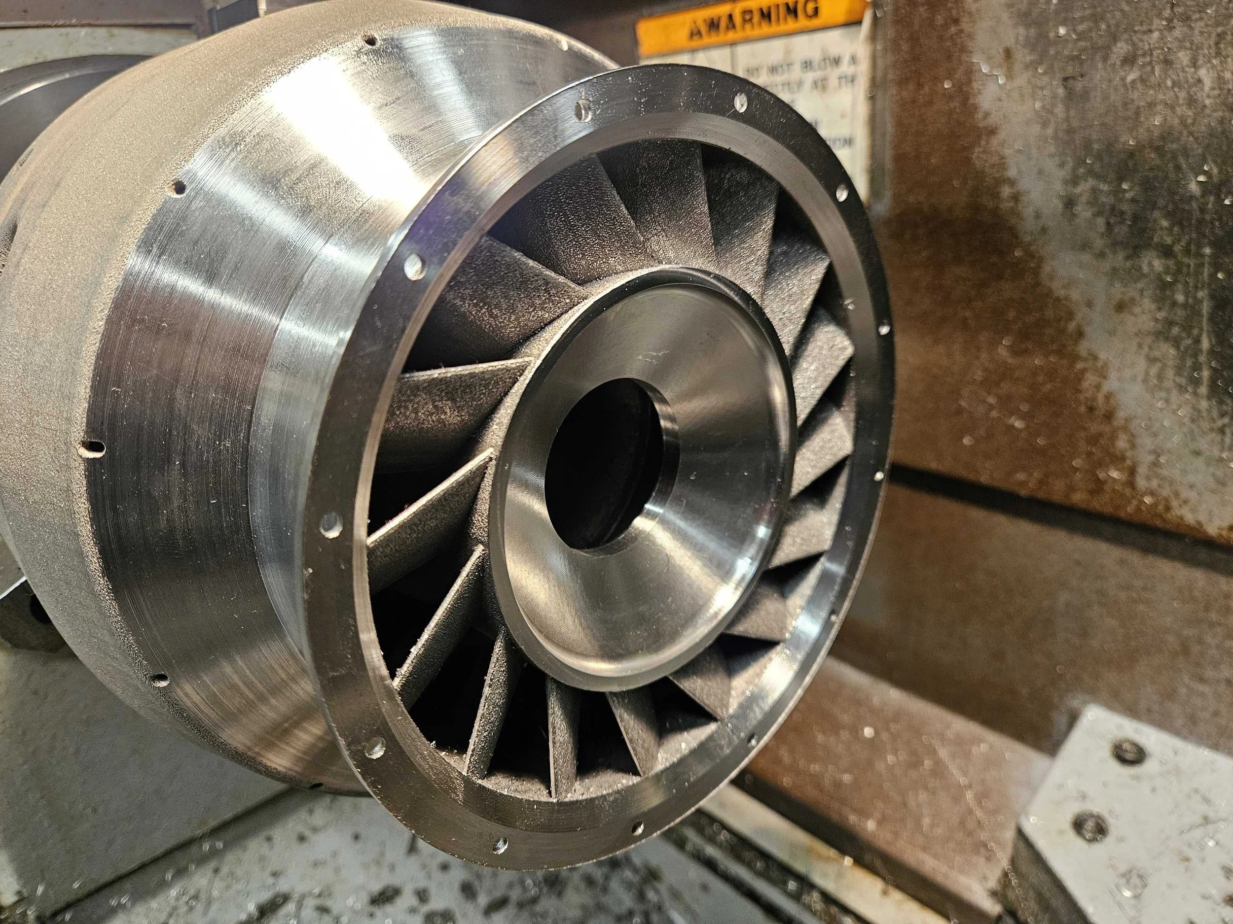
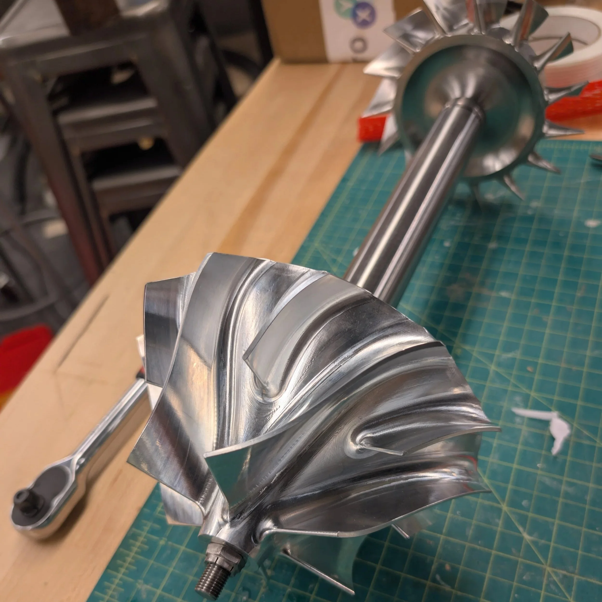
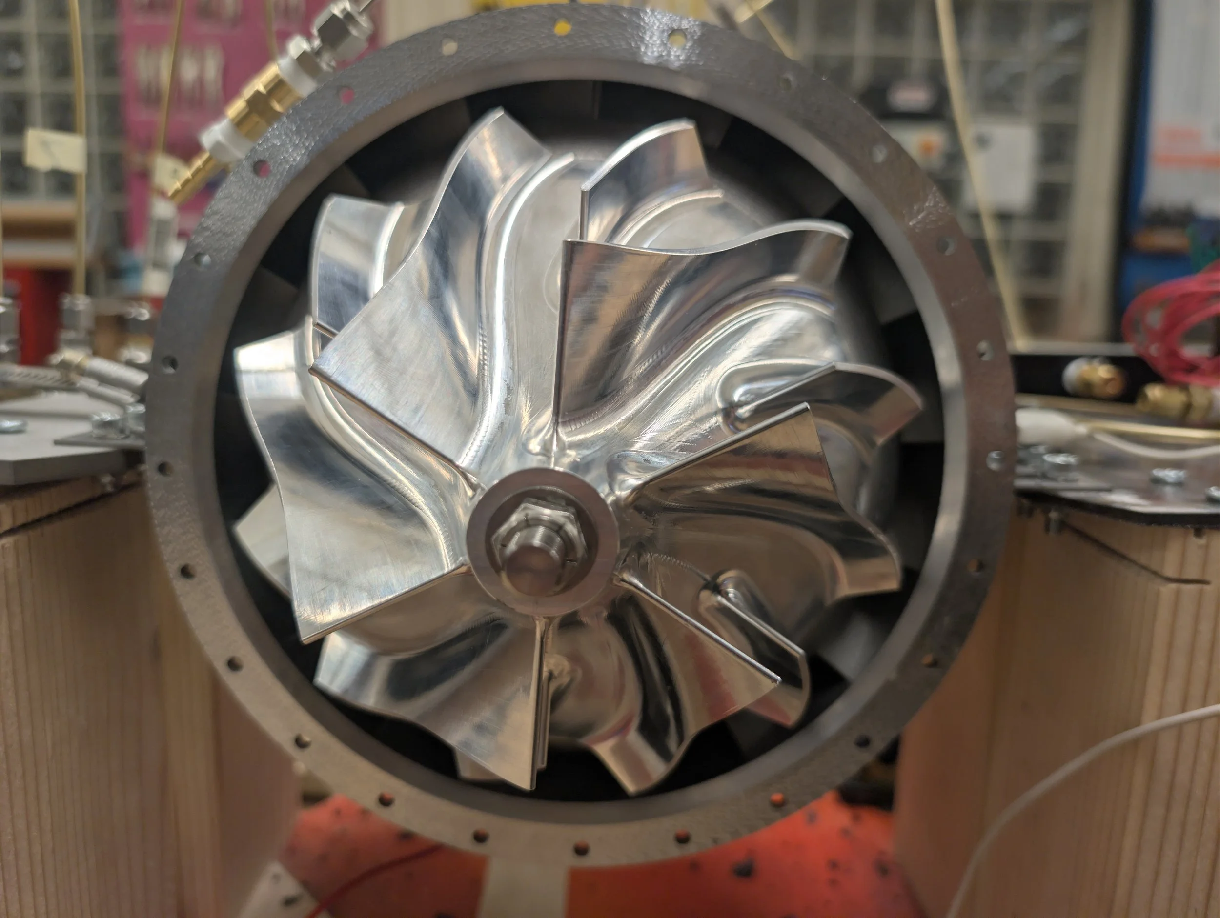
Another significant change we made was to the compressor design. With the radial compressor, the air is redirected at perpendicular to the axis of rotation, and then it needs to be redirected again back in line with the axis in order to flow into the combustor. As it does this, it also passes through two sets of diffuser vanes to cancel out the “swirl” in the air and smooth out the flow that is introduced to the combustor. It turned out that to hit the cycle parameters we set in the first week, our engine was turning out to be 3-4 times the size of the JetJoe engine. At this larger scale, the airflow through the two direction changes and the diffuser vanes of the radial compressor became too turbulent making our compressor too inefficient for our cycle to close. (The compressor would require more energy than our turbine could harvest).
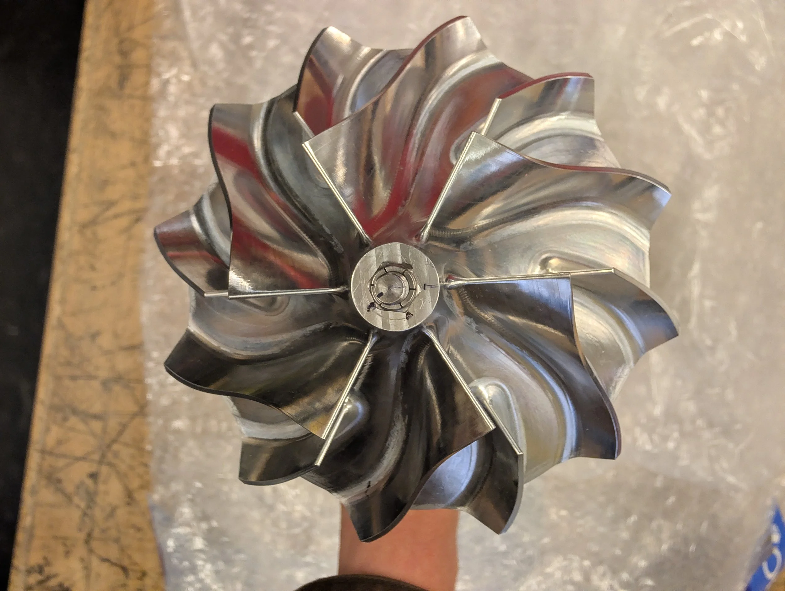
So, over the weekend Ethan devised a new mixed flow compressor (where the air exits at a diagonal angle) striking a compromise between the high compression ratios that can be achieved with radial compressors, and the less torturous air pathway of an axial compressor.
This week I was also able to fix the blade generation issues and settle on a turbine design that had much smaller fillets on blades that could stand up better for the force. One of the only times I found the AI truly useful occurred this week, where I could feed it screenshots of the CFD simulation results of the airflow through the turbine blades, and ask for how the blade geometry could be tweaked to address areas where I found the flow separating or shocks being generated that hurt our efficiency.
We also spent a significant amount of time hollowing out material from both the compressor and turbine to try and reduce how much their imbalances caused vibrations. Yaakov’s access to Ansys helped us significantly with these simulations as it had better models for Inconel (the material for our turbine, a superalloy designed to handle extreme forces at high temperatures), and more powerful tools for FEA simulation in general.
By Friday our combustor and turbine design were essentially finalized, allowing Zach to settle on a shaft design and bearing choice. The results from his ARMD rotodynamic simulation ended up showing us that we were forced to operate supercritically, meaning that as we ramped up the speed of our engine on startup, we would pass through one of the resonant modes on the shaft. While sub optimal, this was not a dealbreaker as long as we ensured we ramped up quickly and spent as little time as possible, minimizing the opportunity for dangerous oscillations to build up around the resonant peak.
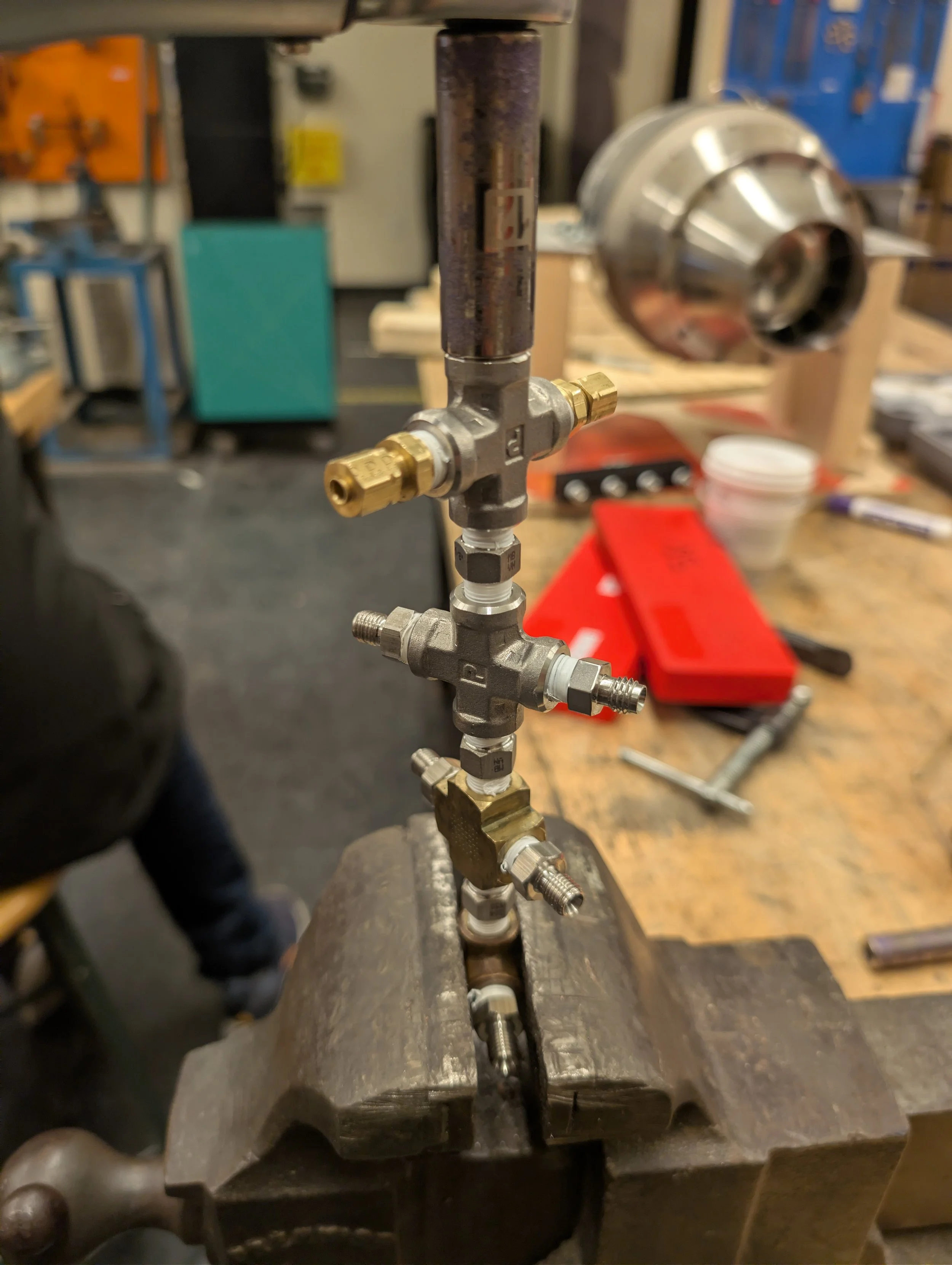
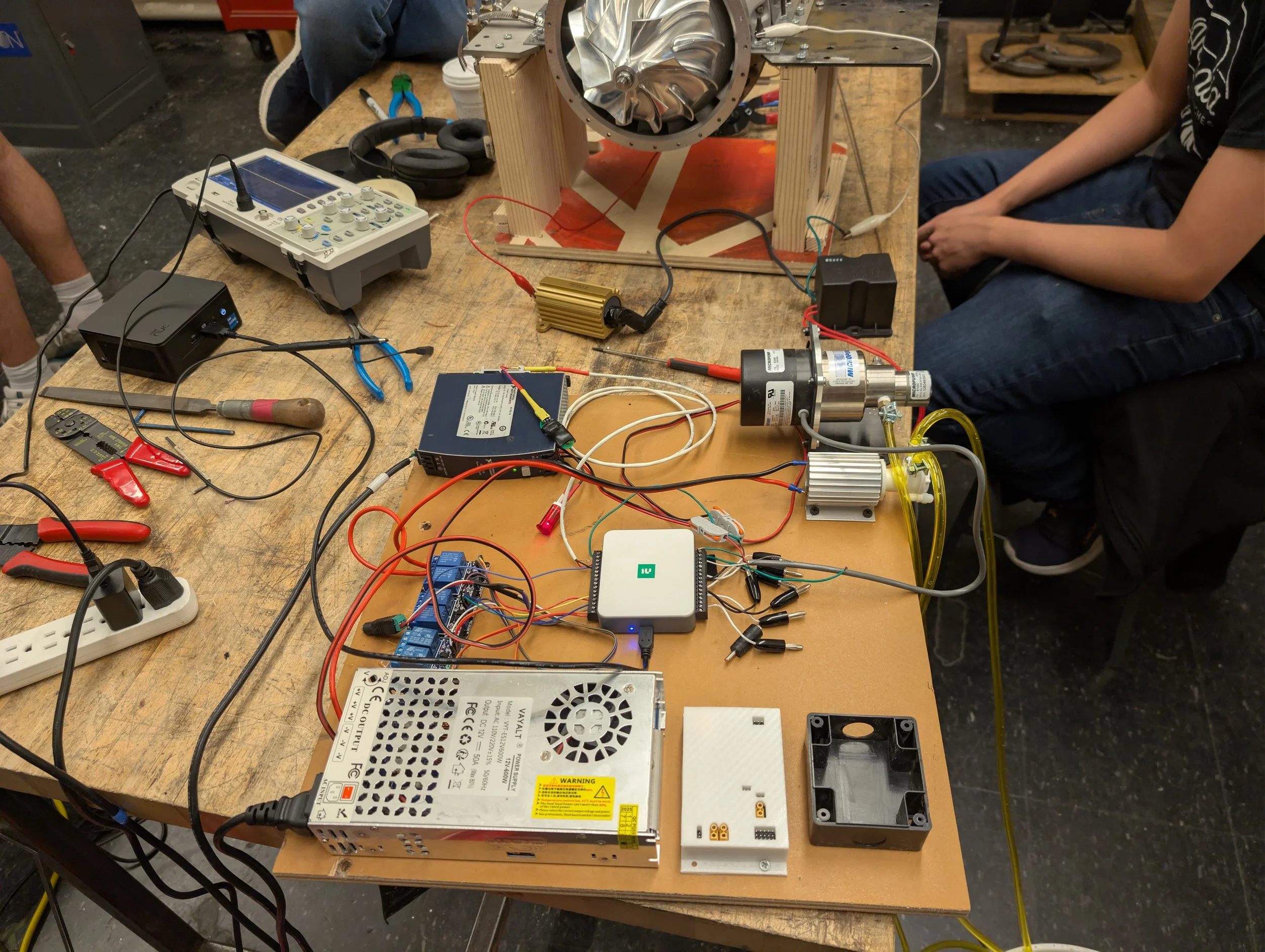
Finally, after settling on the turbine design I also spend some time devising the control system and operation procedures for testing our engine. I sourced valves and pumps to handle the propane and Jet A flow, glow plugs and spark plugs to ignite our engine, as well as relays, speed controllers, temperature sensors and RPM sensors to give us full control and visibility into everything our engine was doing. We even overnighted open source engine control units from Bahrain.
By the end of this week we had a pretty good idea of what each component of our engine would look like, and a plan to address all of the staff’s concerns with our design. The bulk of the work remaining was in fitting all our components together, and sourcing all of our parts.
Simulation and Risk Mitigation (January Week 3):
This week was almost entirely spent in Solidworks CAD, making all of our disparate parts that had been designed by separate people integrate together into one assembly. This week was when our AI usage dropped the lowest. During the first two weeks we occasionally consulted the LLMs for assistance with the software packages we were provided (probably its most helpful use case in our experience), for general sanity checking of architectural changes, and for some guidance on areas of the process various people were unfamiliar with. In general the team usually deferred to our own learning from classes, internships and textbooks rather then relying on the LLMs, and we would rely on each other to help us when we got stuck. One of the teams even got cut because the LLMs misled them into making a design that was unsalvageable. By this week, all the work was in Solidworks which the LLMs had no way of contributing to, so we barely used them at all.
Our main concern with the assembly of the engine was maintaining concentricity and appropriate tolerancing of the entire stackup down the length of the engine. Both the compressor and turbine benefit from the tips of their blades to be as close as possible to the shroud around them, but some clearance must be maintained so that they do not rub especially when the parts expand under centrifugal loading. This tip clearance gap is 0.2-0.3mm, so if any of the parts are off axis by more than that amount, or if the height of any of our parts differs by around that amount (since the shroud around both compressor and turbine is conical), the parts will rub.
In order to ensure all our parts came together without misalignment, we spend a lot of time this week designing mating tapers and bolt flanges at each of the interfaces. The tapers forces the centers of the parts that meet to coincide. Having the shaft contained within a shaft tunnel that holds both bearings enforces that the two bearings are perfectly aligned so the shaft can turn smoothly.
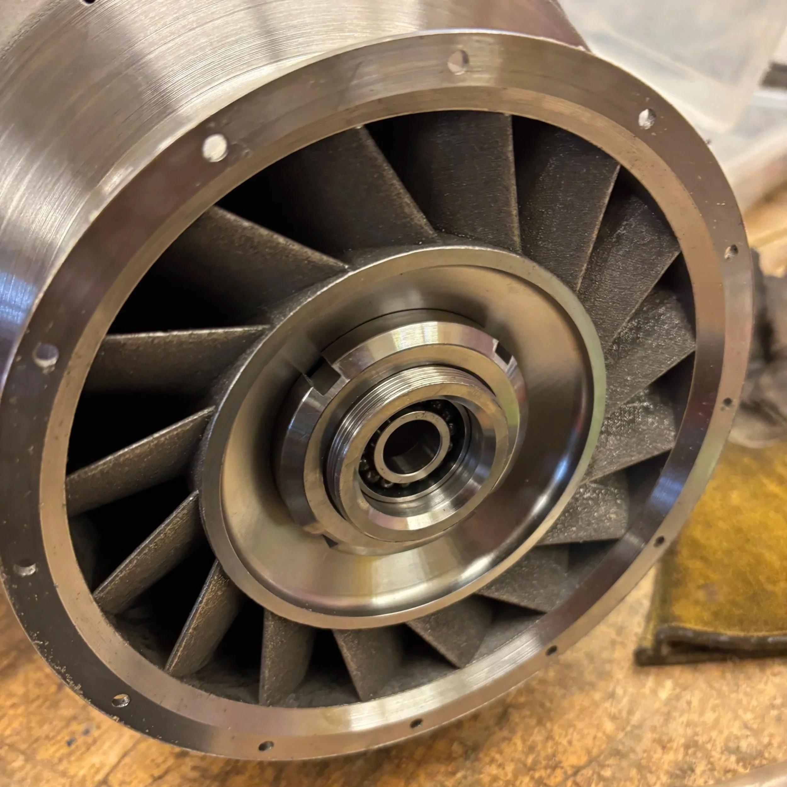
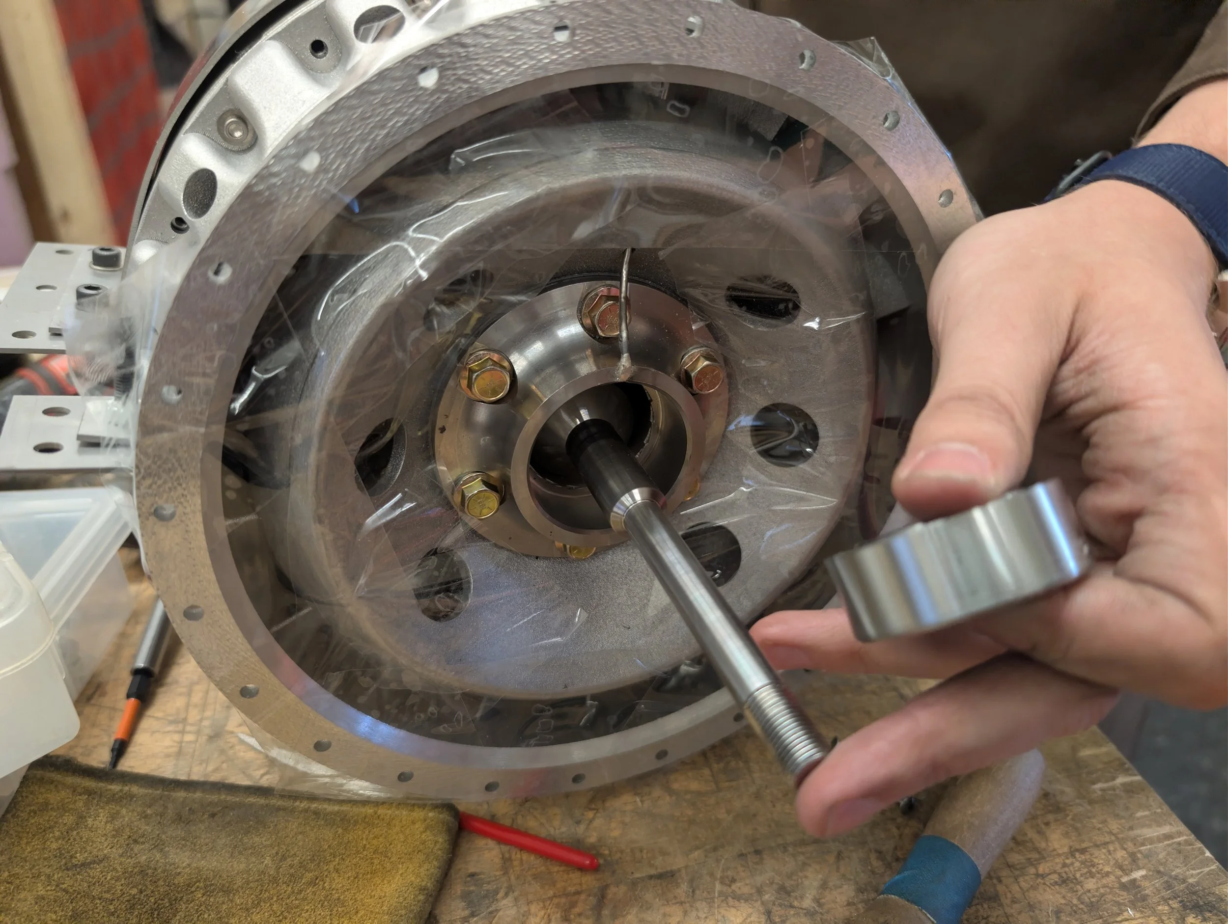
Finally, I planned out the assembly sequence and the stackup of the entire rotating assembly. There were a few important considerations to be made here. Firstly, we would be using angular contact ball bearings to support our shaft, which are designed to take both radial forces (which would be present due to vibrations) and axial forces (which would be present due to the forces of the air flowing through our compressor / turbine and the thrust generated). Angular contact bearings require a precise amount of preload force squeezing them together when they are installed in order to perform properly. Secondly, we found in our rotodynamic simulation that rigidly mounting the bearings brought the resonant peak of the shaft up too close to our operating region, so we wanted to soft mount our bearings on O-rings. We also needed some way for torque to be transmitted from the turbine to the compressor in order for the energy harvested from the exhaust gas to close the loop and power the compression. All of this had to be done while ensuring that the turbine and compressor were precisely located on the shaft to ensure the tip clearance gap was maintained, and lastly it all had to be possible to assemble and disassemble knowing that it would be impossible to reach certain parts in the rotating assembly once the engine started getting bolted together around it.
At the beginning of the week I drew up a sketch explaining how to solve these issues to the rest of the team. The compressor would be slid onto the shaft with a taper fit (to transfer torque and locate it axially) that would be forced together by a nut ahead of it. Both the bearings would be on O rings, which we could buy of various rubber hardnesses to tune the rotodynamics. The forward bearing would have a wave spring behind it, applying a preload force that we could tune based on how much the spring would be compressed once everything ended up in its final position upon assembly. With these parts together the rotating assembly could be slid into the half assembled engine, and then the turbine threaded on from the rear. A thread on the turbine and a final jam nut after it would allow for torque transmission on the rear also.
By this time, the combustor design was also finalized and integrated into the rest of the assembly, with holes for spark plugs and glow plugs to ignite the engine. Additionally a full test plan was written up for the subscale combustor.
Finalization and Sourcing (January Week 4):
In the last week of January, with the go ahead from the course staff we finalized all our parts and sent them out to various vendors for fabrication. For all of our machined parts, we created engineering drawings calling out the necessary tolerances on the faces that had to precisely fit together.
To verify our rotodynamic results (the ARMD simulation required a number of assumptions to be made due to limitations in the software) we simulated our rotating assembly again in Ansys Modal and tweaked the design of various components to increase our safety margin.
Our presentation for the final design review shows the final geometry of each part and the supplier it was sourced from, as well as detailed modal results.
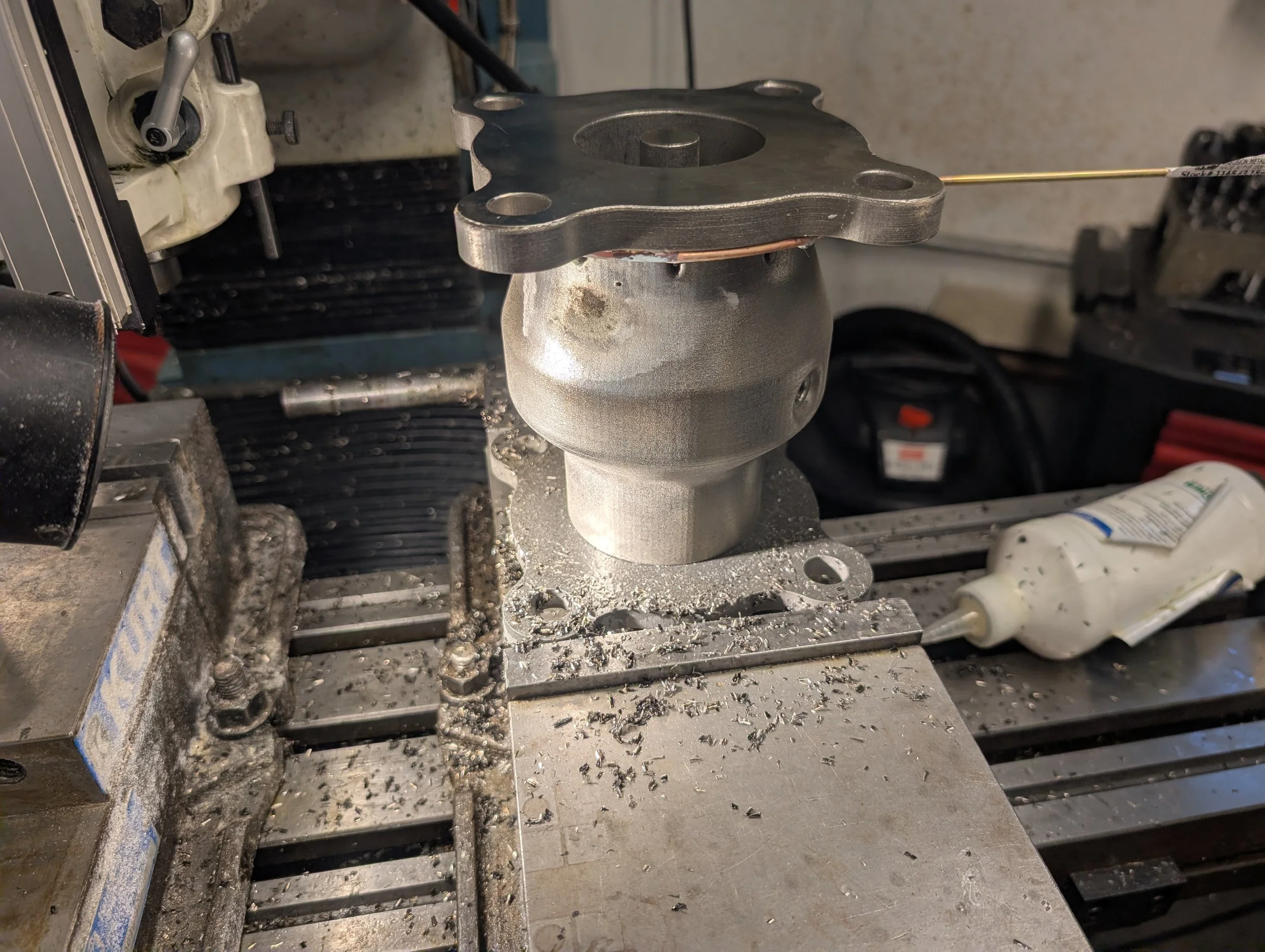
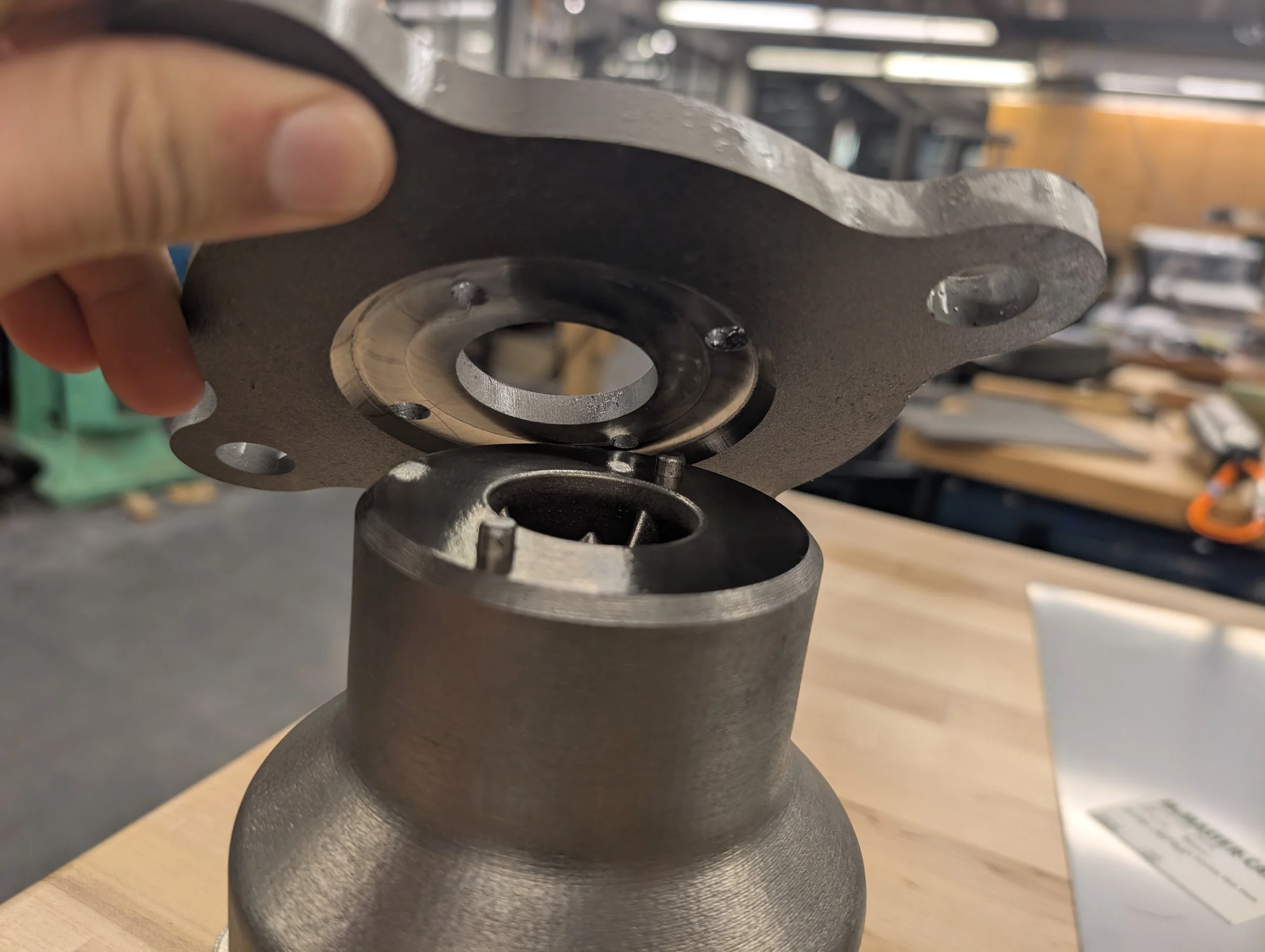
Preparation FOR SuBscale Testing (1ST Week of March):
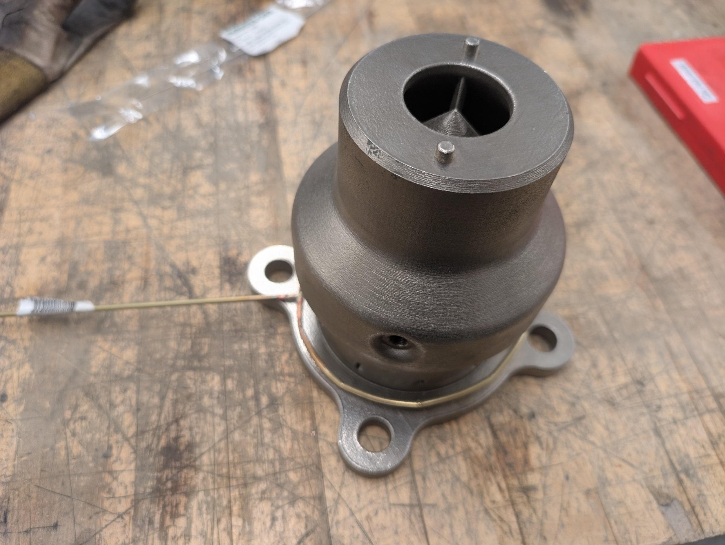
One of the firsts part to arrive from the manufacturer was our 3D printed subscale combustor. In order to make it printable, one of the flanges had to be removed, so I was responsible for fabricating that in house in the AeroAstro machine shop:

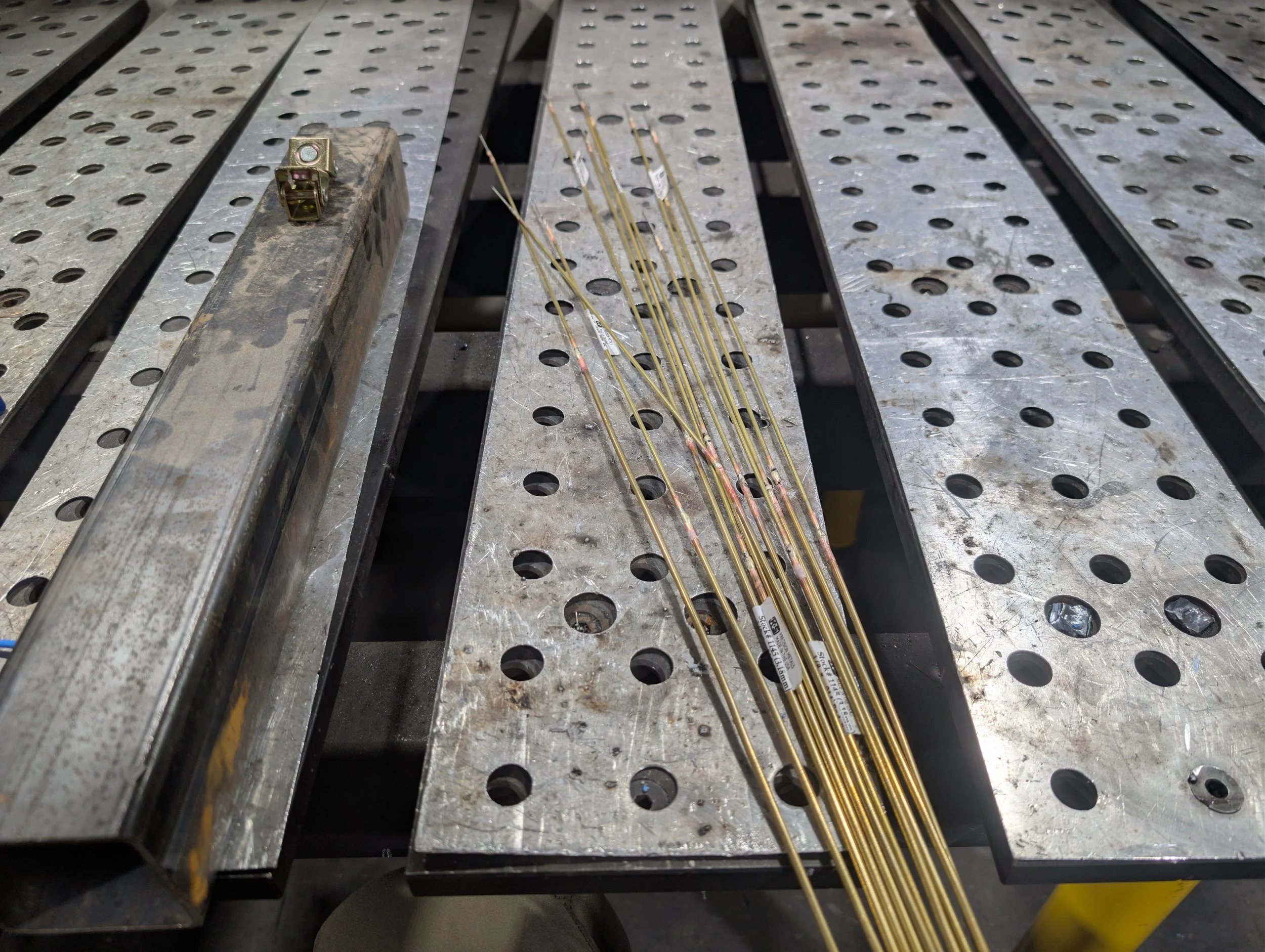
We also had to fabricate a manifold to feed propane and Jet A into the combustion chamber. Our intent in the design phase was that we would braze together a ring of brass tubing for Jet A with 12 spokes leading into the vaporizer tubes of the combustor. Additionally, 4 holes in the combustor were enlarged to accept a second tube carrying propane adjacent to the Jet A line.
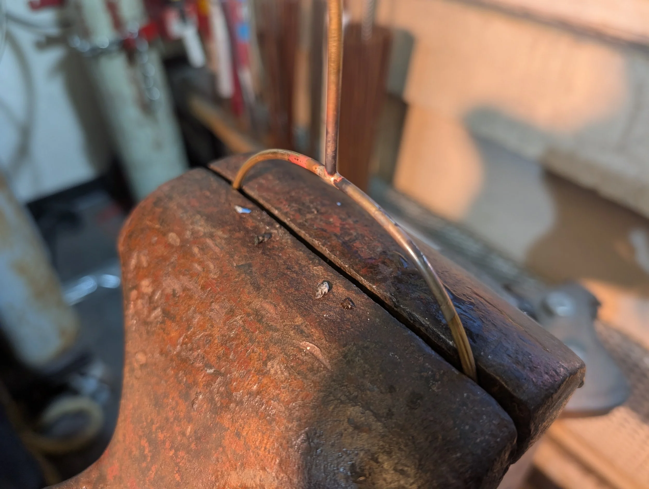
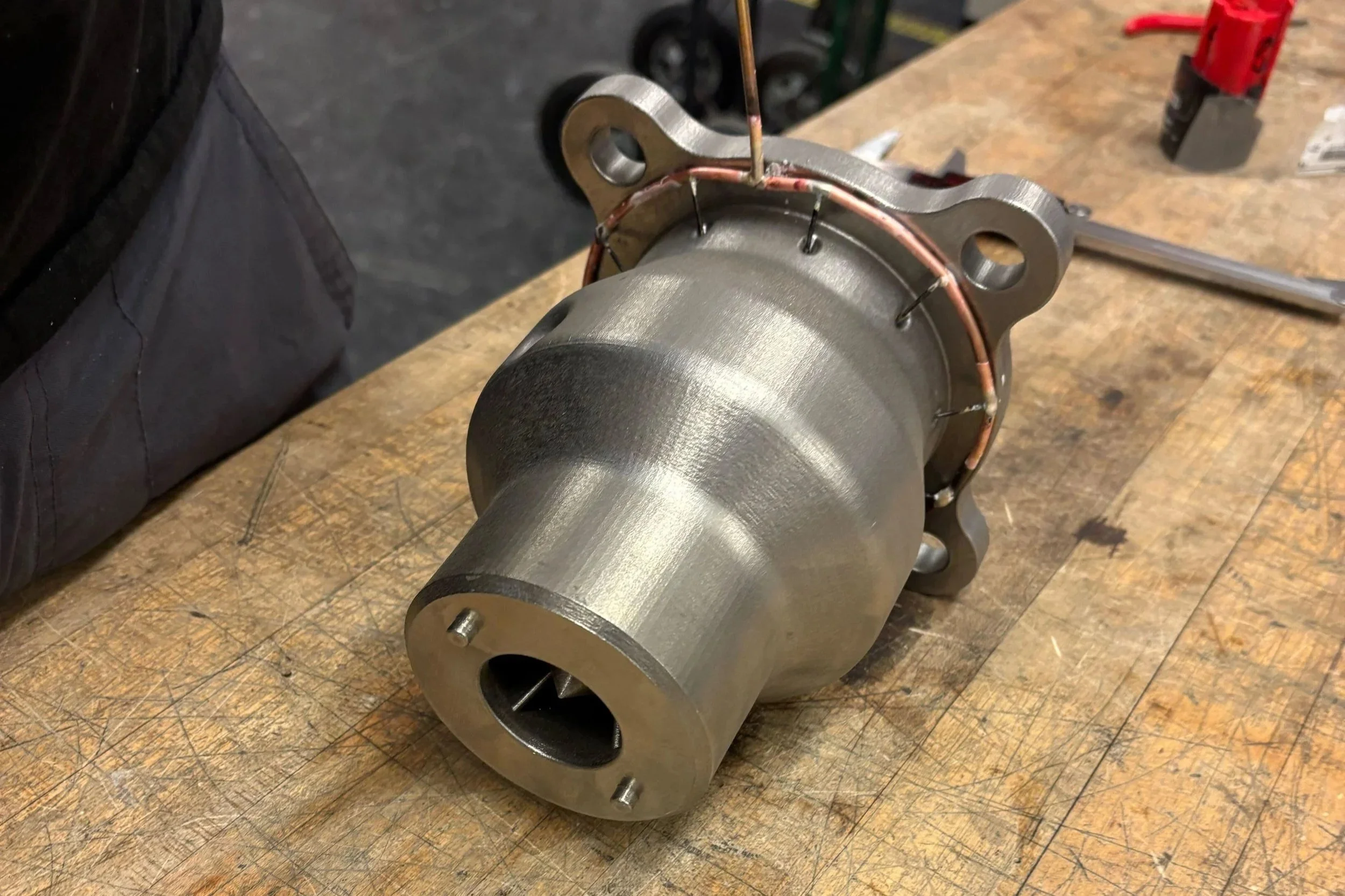
We had originally hoped to be able to braze these tubes directly into the Inconel, but it turns out that no matter what brazing alloy, flux, or preheating method we used, the braze would not stick to the Inconel. So we had to settle for sealing the region around where the fuel lines entered with firebrick sealant, a sort of clay. This had to be done once the combustor was installed in its final position in the testing jig.
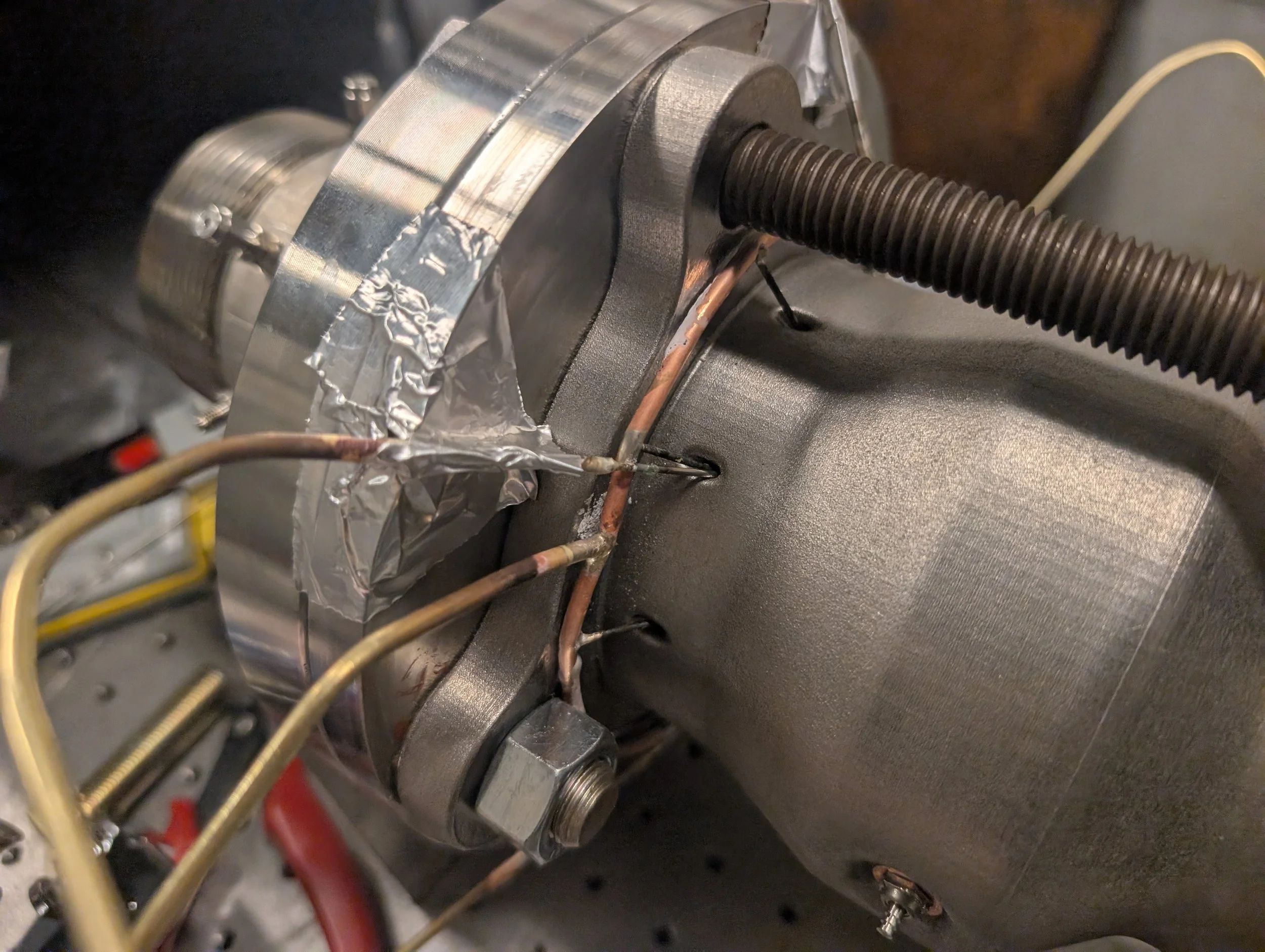

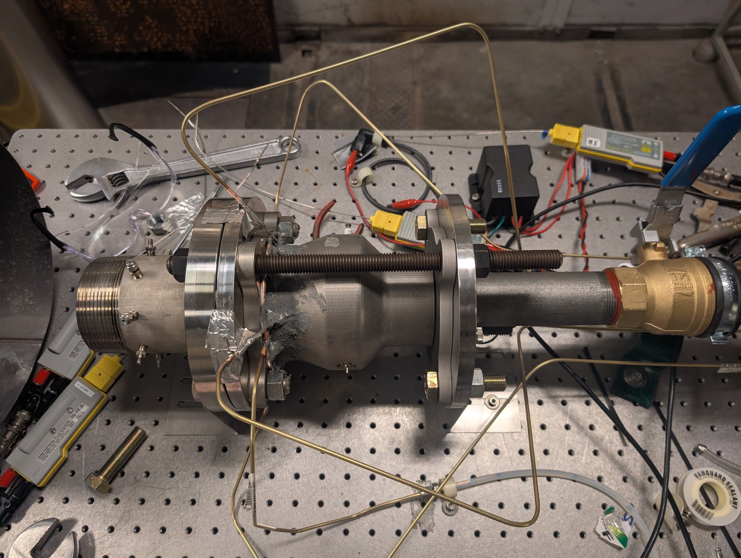
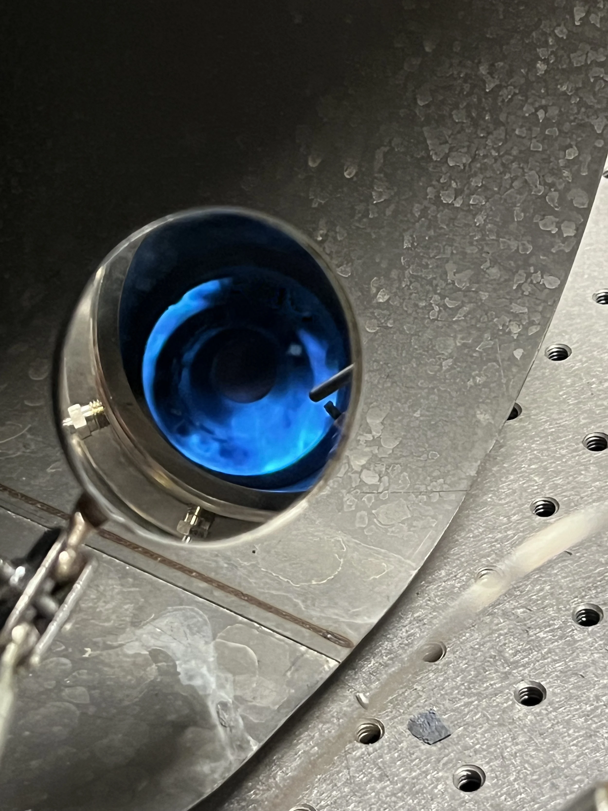
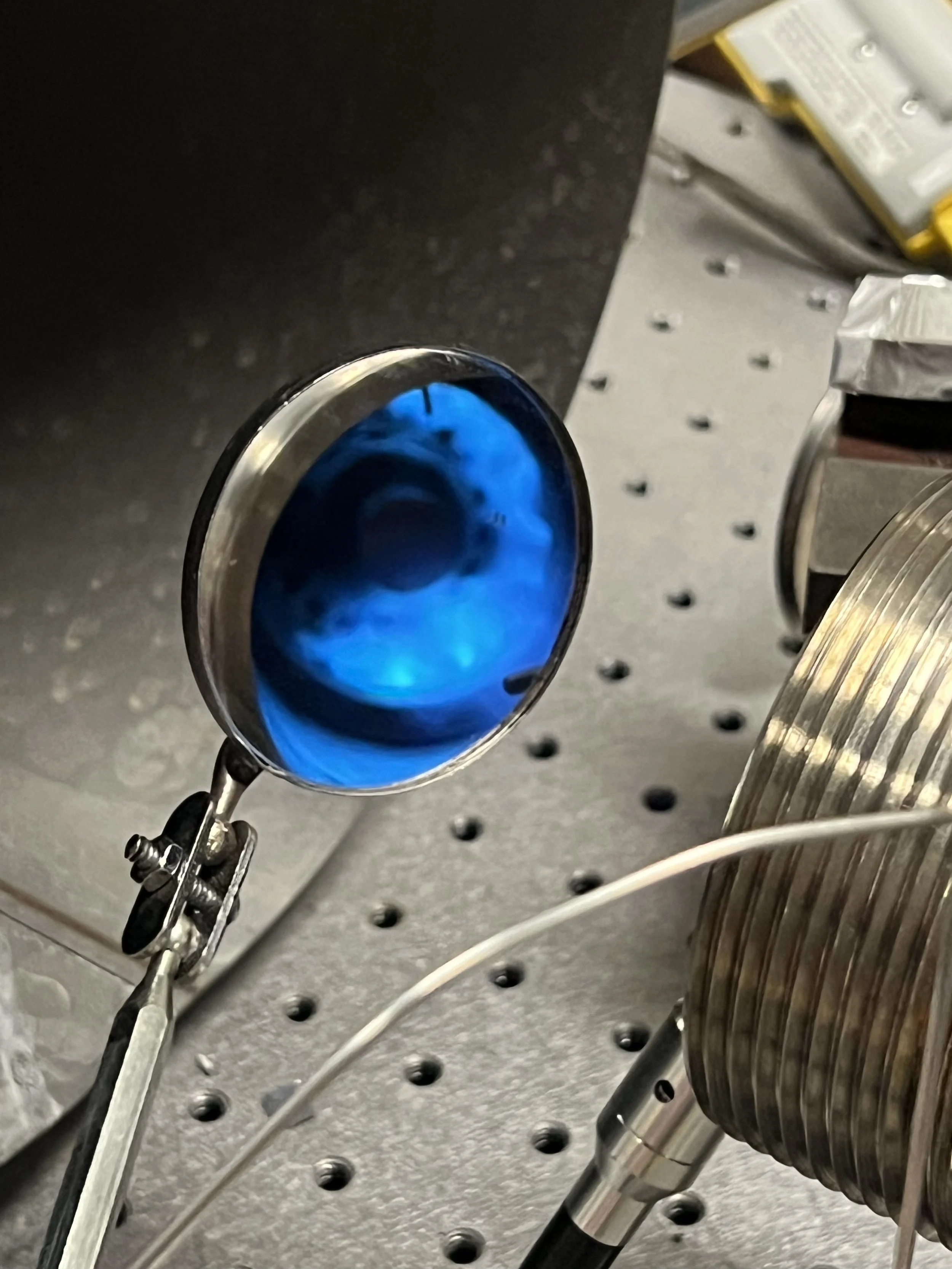
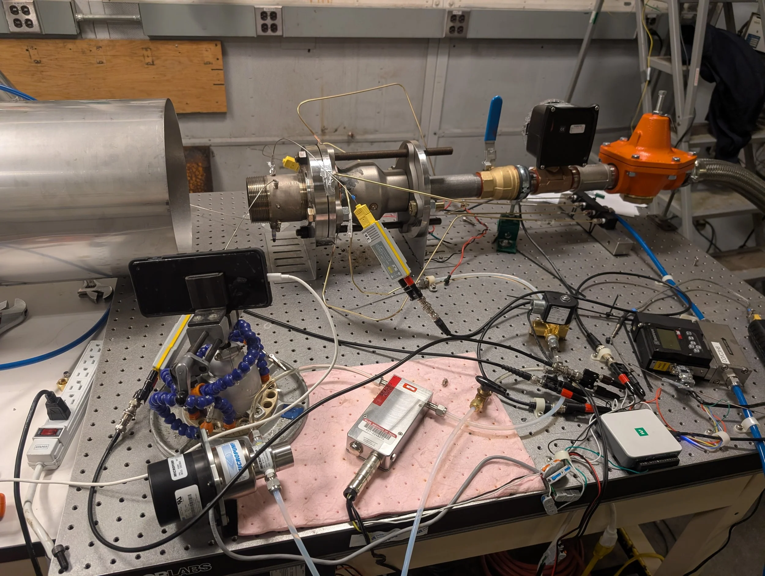
SuBscale Testing (March 5):
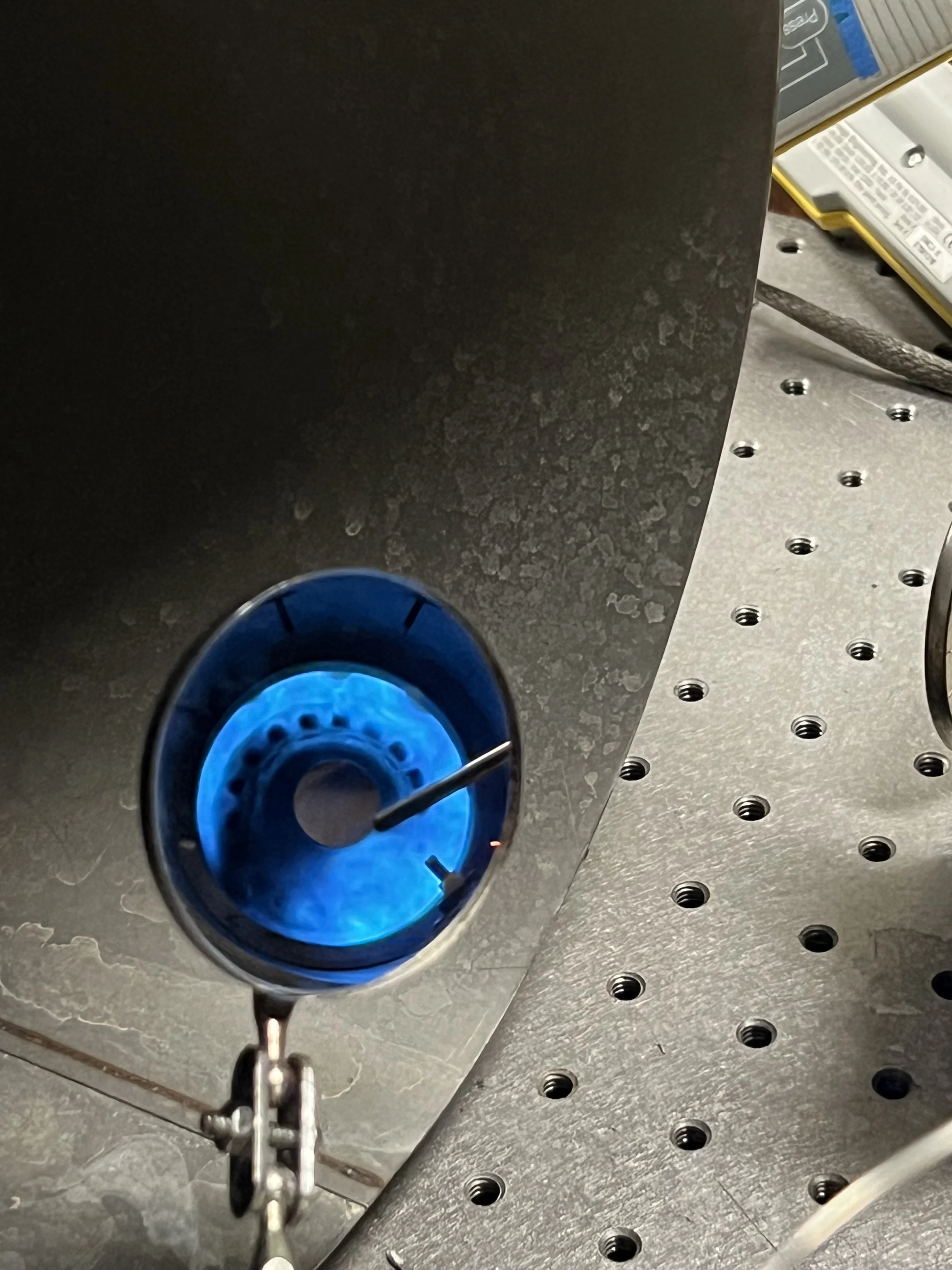
With all the tubing, ignition systems, and thermocouples hooked up we set about testing the subscale combustor. We had a lot of issues igniting the engine initially. We discovered that the glow plug was useless since the hole for it was too far from where the propane was being introduced. The spark plug worked if we turned the air flow down, giving time for the propane-air mixture to distribute throughout the combustion chamber. After several tries we were finally able to ignite and sustain a flame, but it was slightly lopsided likely due to some fuel lines having a more restricted flow due to being partially clogged with braze, or pressure drops in the tubing meaning the flow velocity out of all the fuel lines was not the same.
Unfortunately our test got cut short due to the firebrick sealant not fully sealing around the fuel lines and causing unburnt fuel to drip onto the testing apparatus. Since the full scale combustor was already ordered when we discovered the issues brazing to Inconel, we would have to content with the same problem on our full engine. Luckily people wouldn’t be standing as close to it when it would run, so the course staff said they would be slightly more lenient with leaks.
Below are some highlights of the subscale test.


Full Scale PReparation (MID APril):
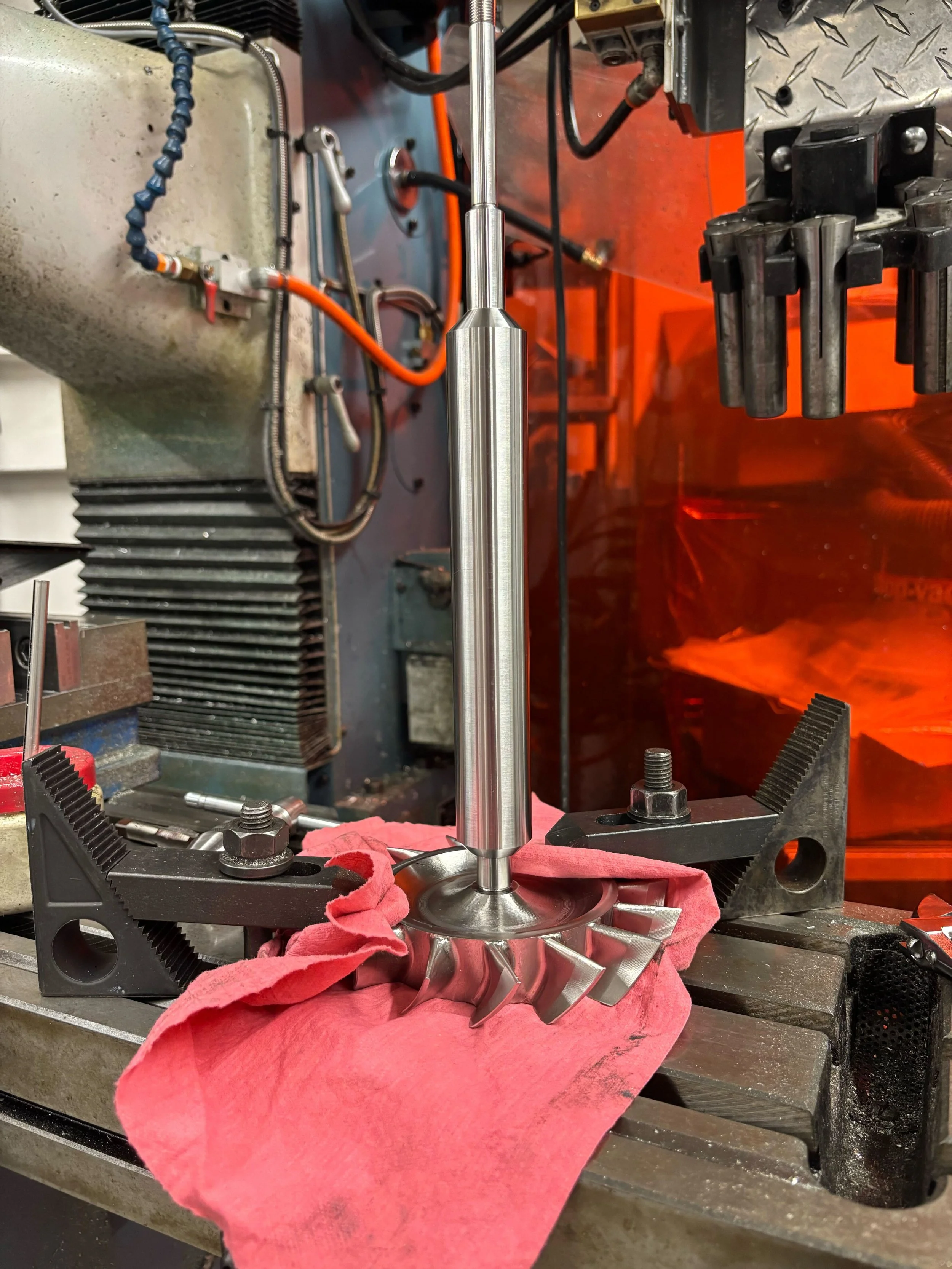
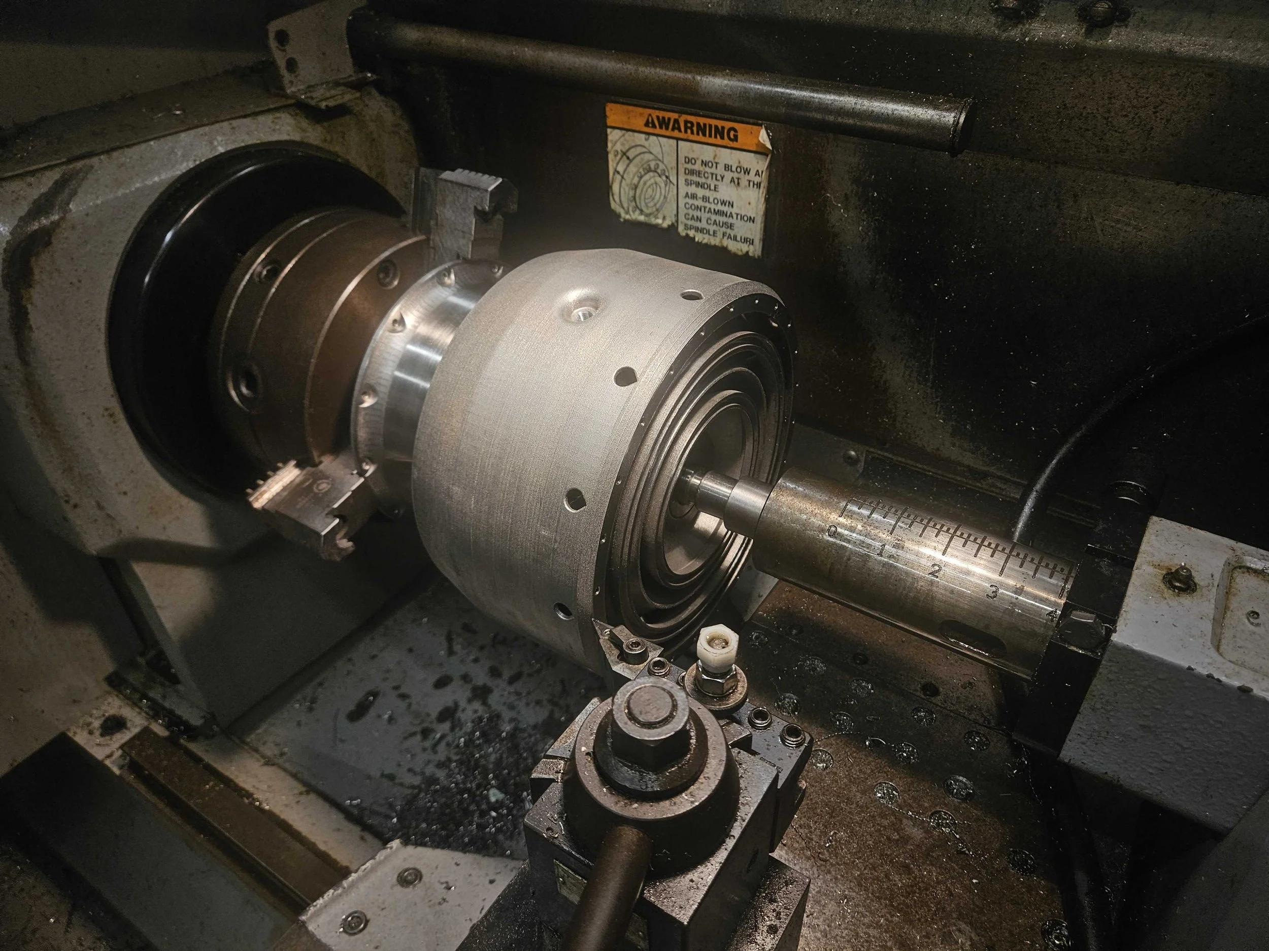
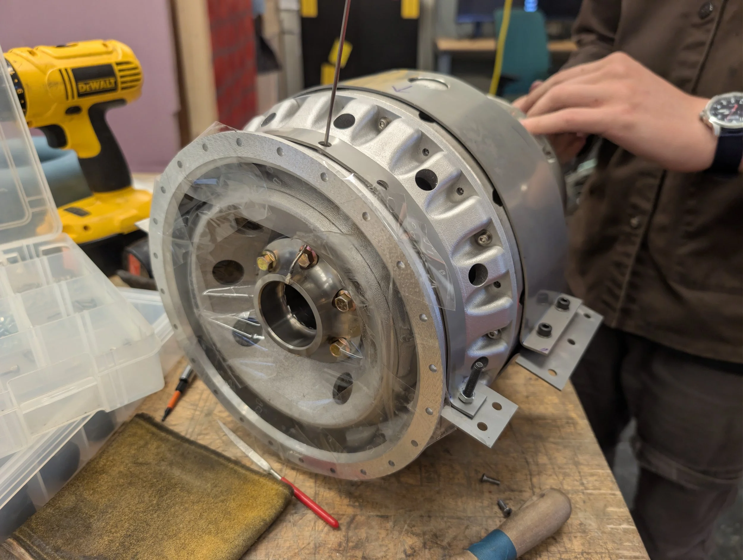
Over the course of March, our various parts arrived for the full engine. Although metal 3D printing technology has come a long way, the parts it produces still have a somewhat rough surface finish and are not perfectly dimensionally accurate. So once the parts arrived, we still had to post machine the precision mating faces on them to ensure all our taper fits worked out to align the parts.
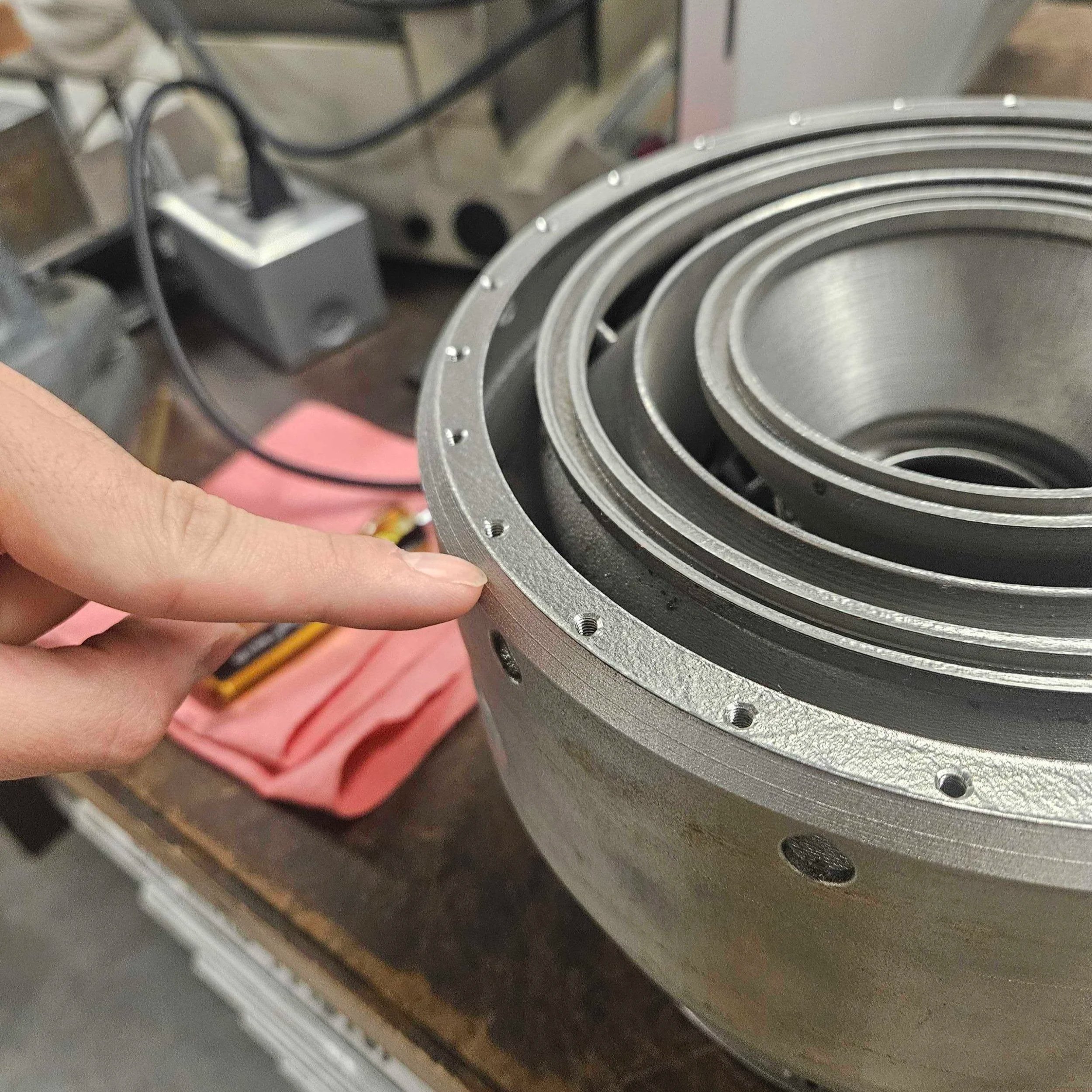
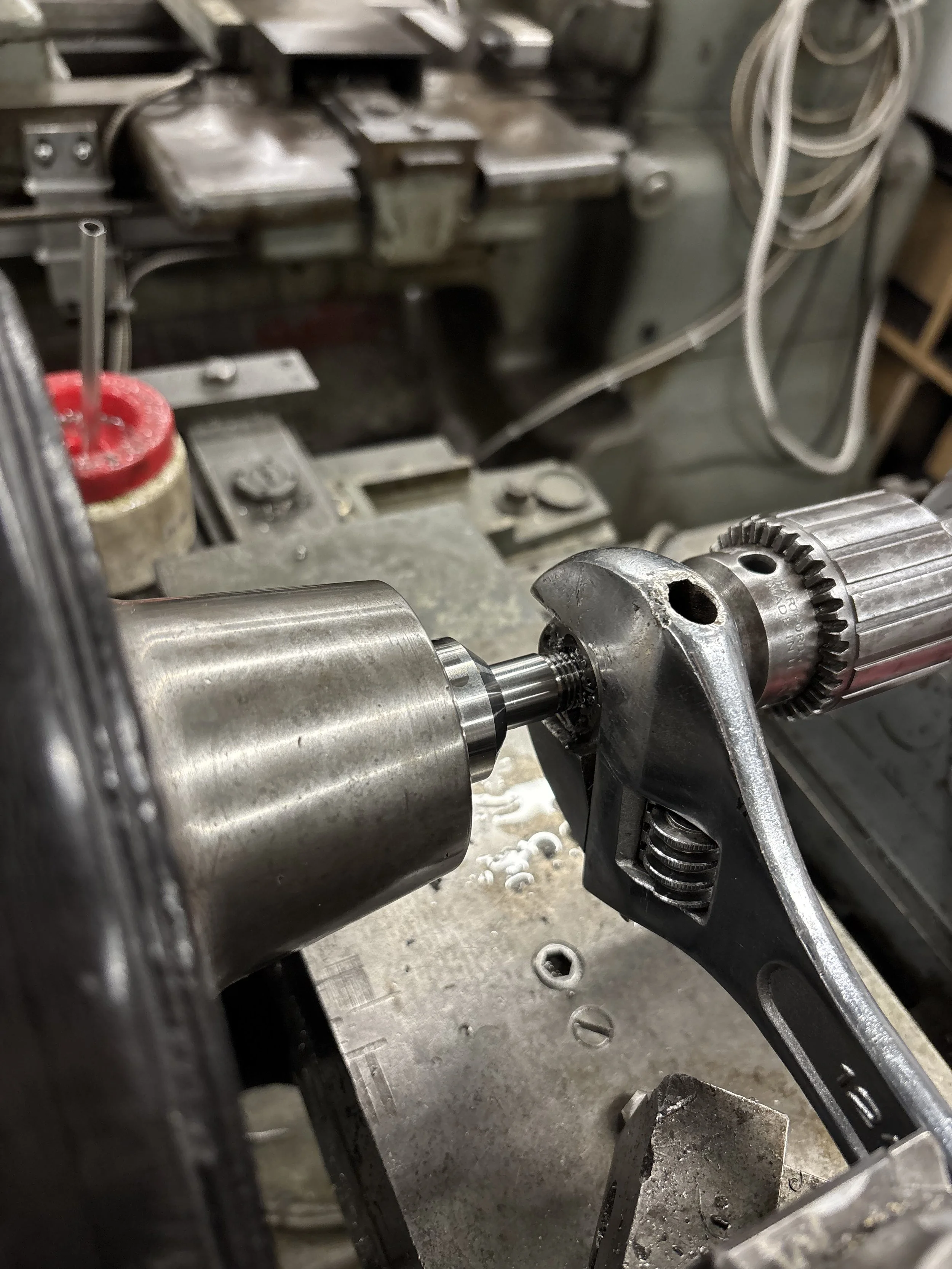
We dry fitted all the rotating components together on the shaft, and sent the assembly out for balancing. A mark was made on each of the parts to ensure we could put them back together with precisely the same clocking as they had been balanced in.

Another issue we had to solve was the compressor shroud. We were not able to find a supplier who could machine it in time, so we ended up having to get it SLA 3D printed. The SLA material that was used for this had a heat deflection temperature very close the temperature of the air post-compression, so we were worried the combustor shroud would deform and fail. So we wrapped it in a layer of fiberglass and epoxy to give it additional stiffness.


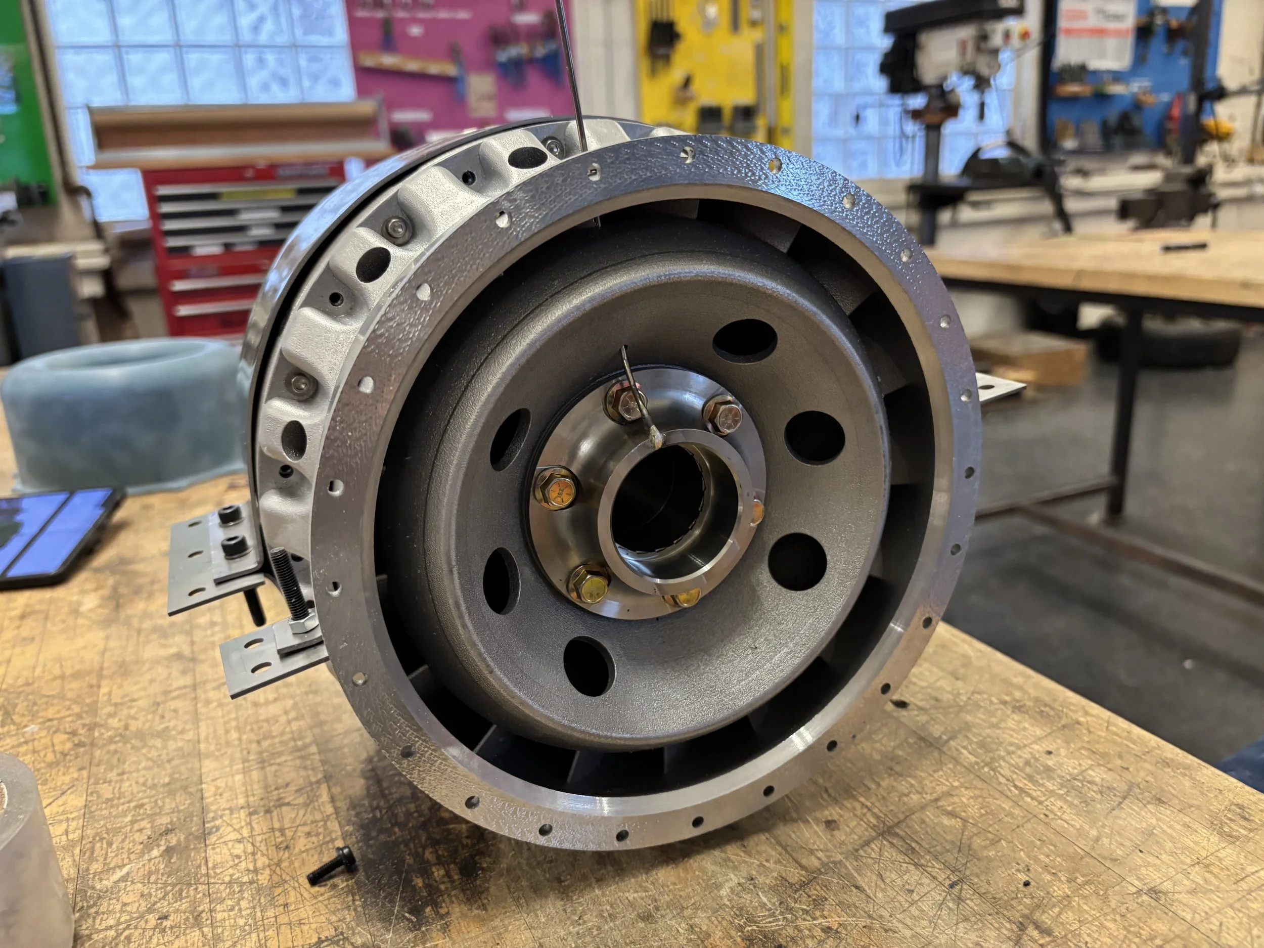
Once everything had been balanced and post machined, we put the entire engine together.


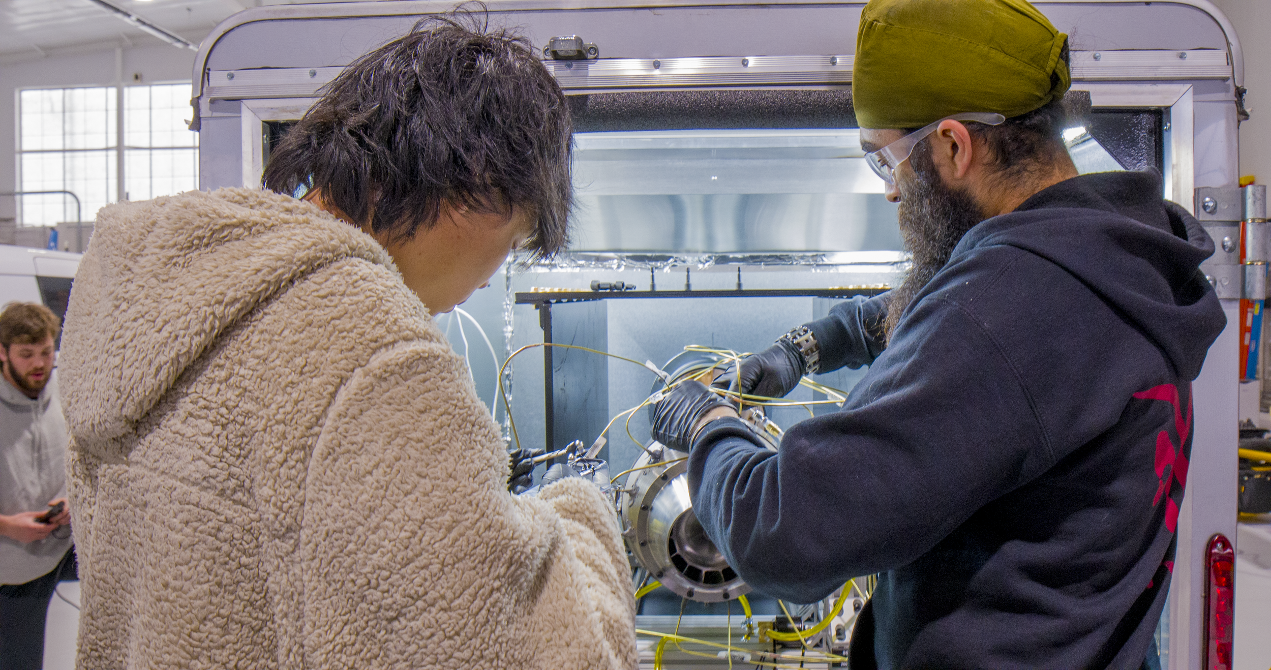
To avoid the unequal flow issue we encountered with the subscale, each fuel line for the big engine was separate. I brazed twelve individual fuel lines, and tested each one with compressed air before it was installed. Eight of them were joined together on one manifold for Jet A, and four were on a second manifold for propane. We also installed wings to mount the engine to the test stand, and solenoid valves to control the fluid flow.


Since some of the parts arrived last minute, all this was done over the course of two almost 20 hour days. Our testing trip left early in the morning since we had to drive to New Hampshire, so the night before our testing trip I got only 80 minutes of sleep.
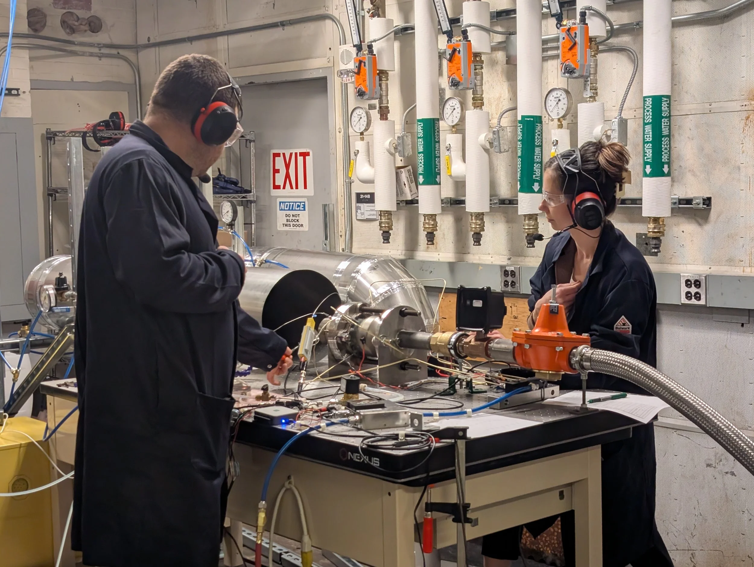
Full scale Testing (April 22):
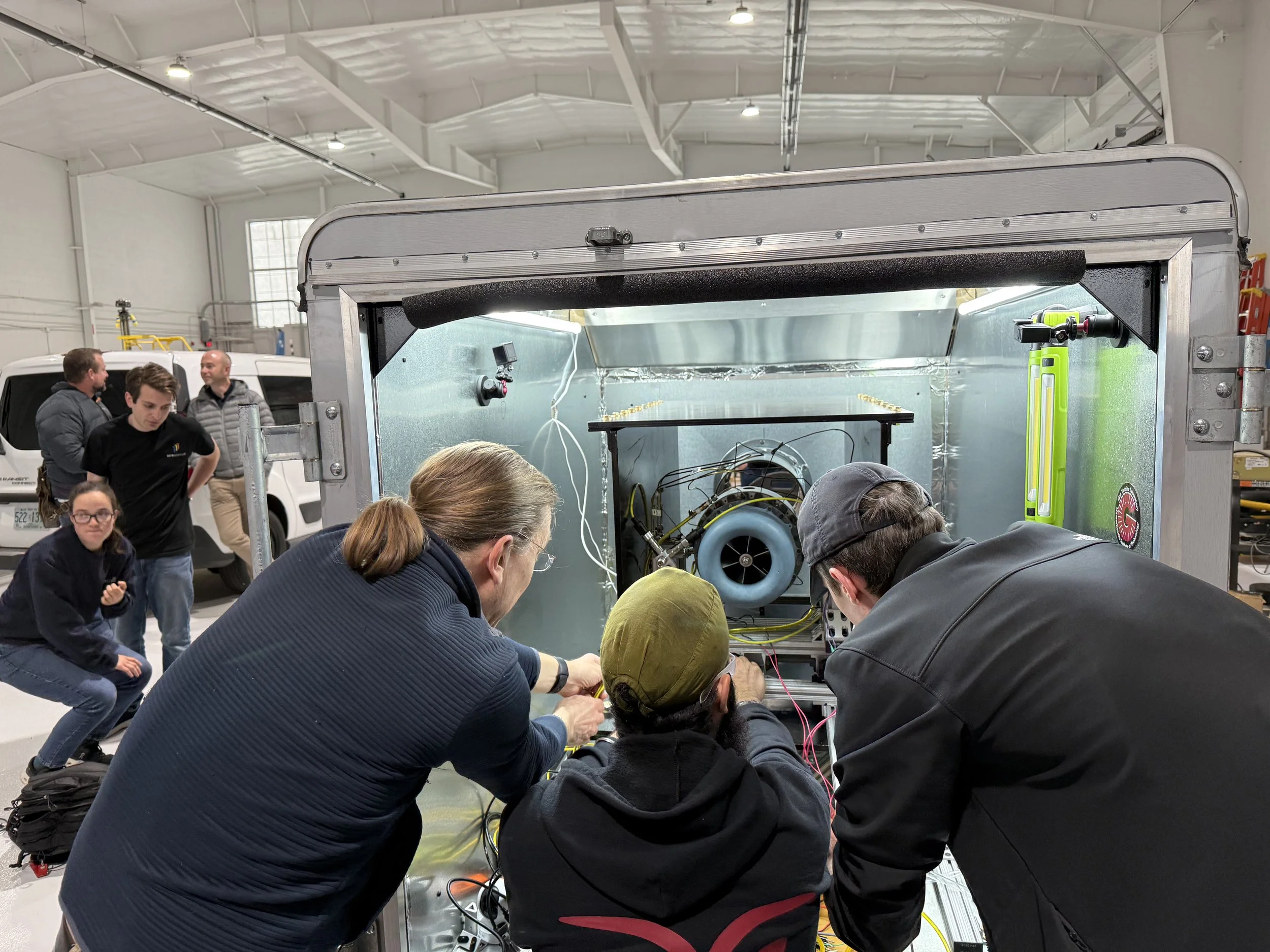
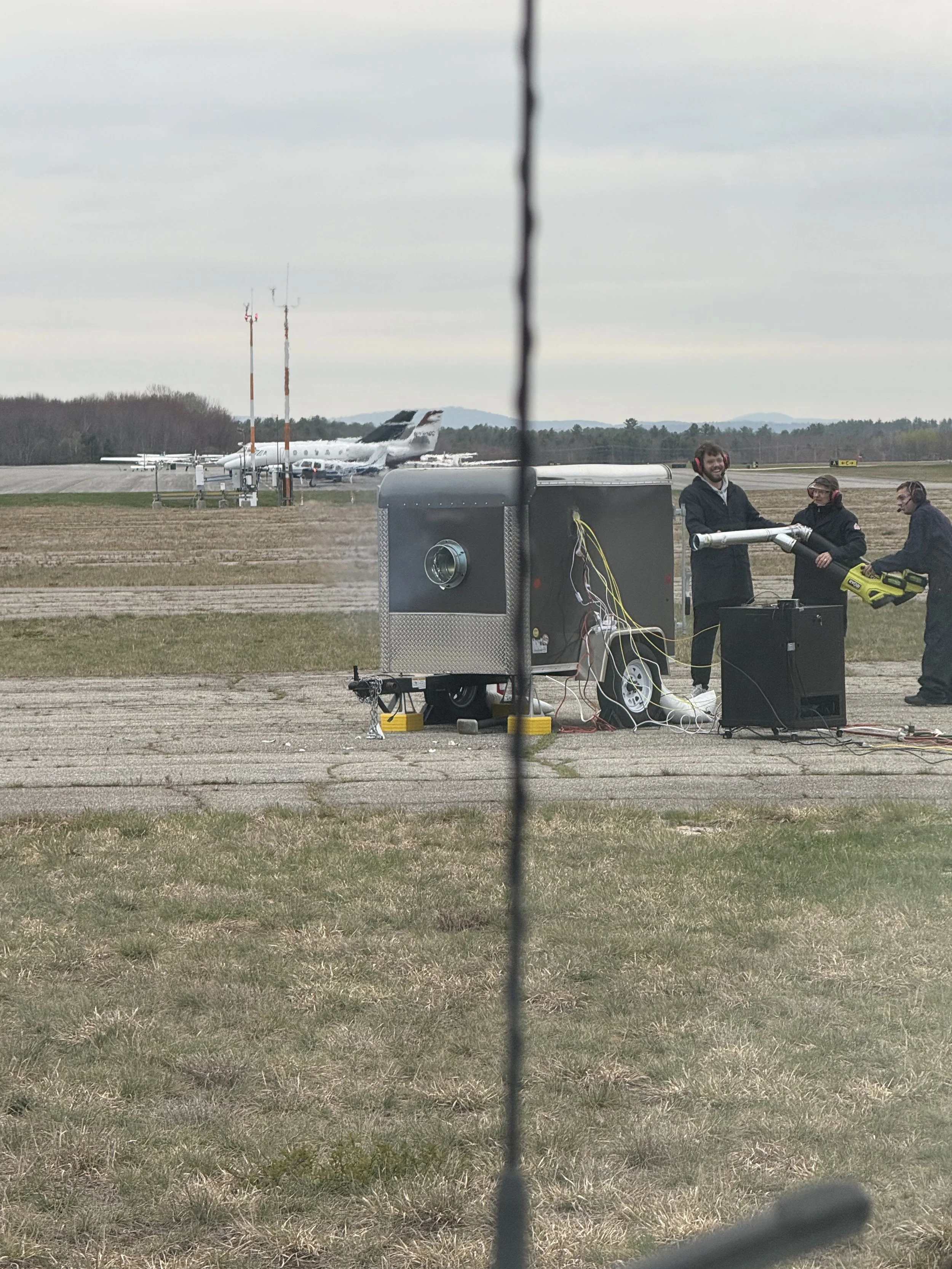
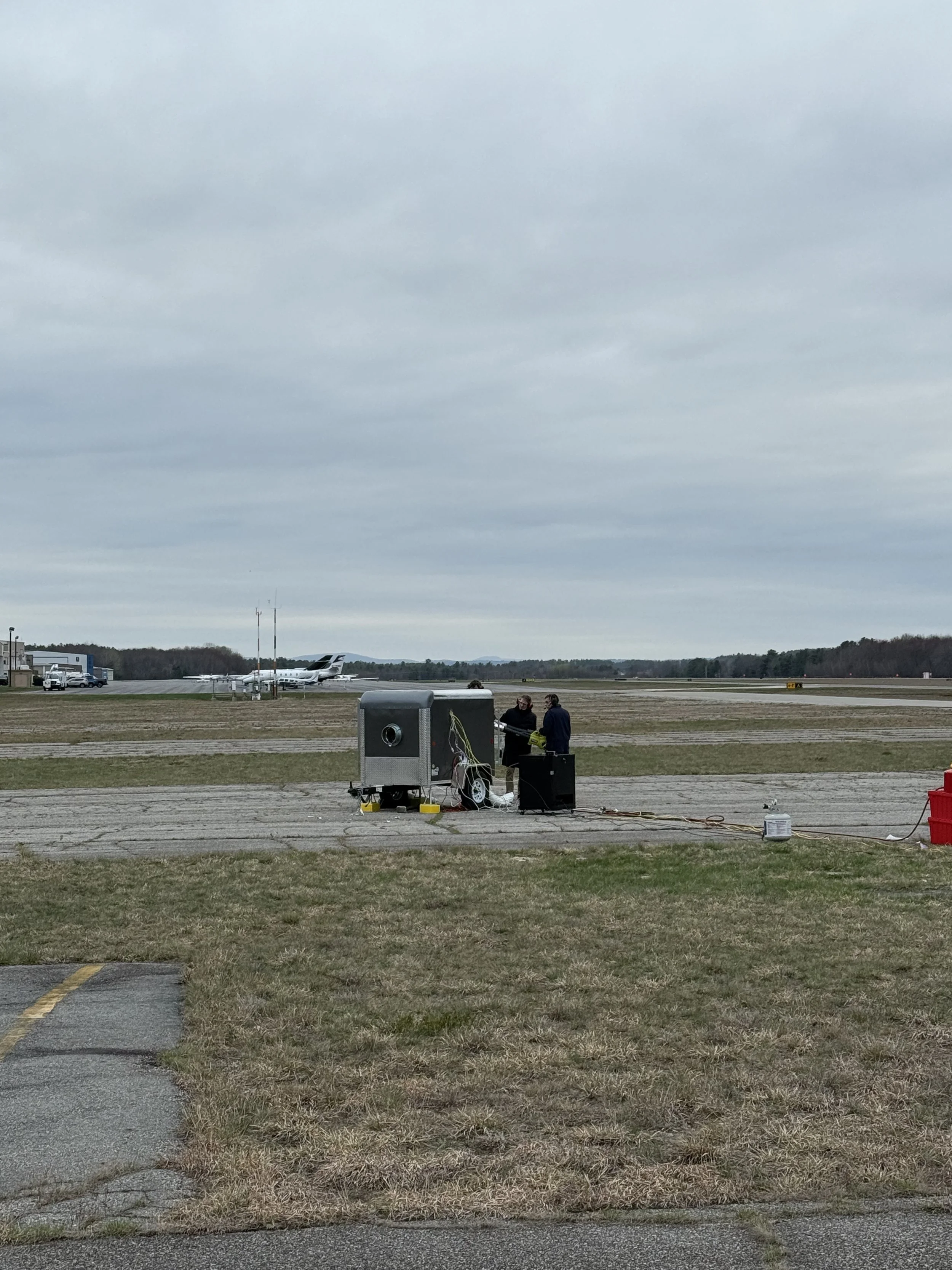
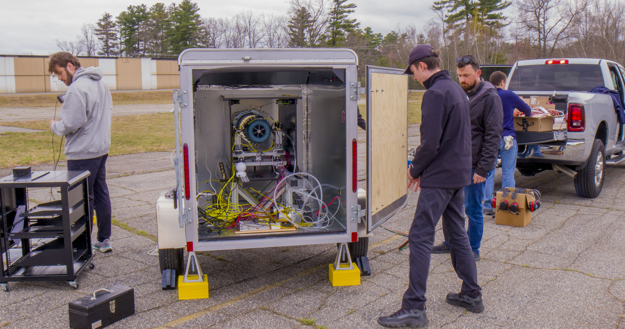
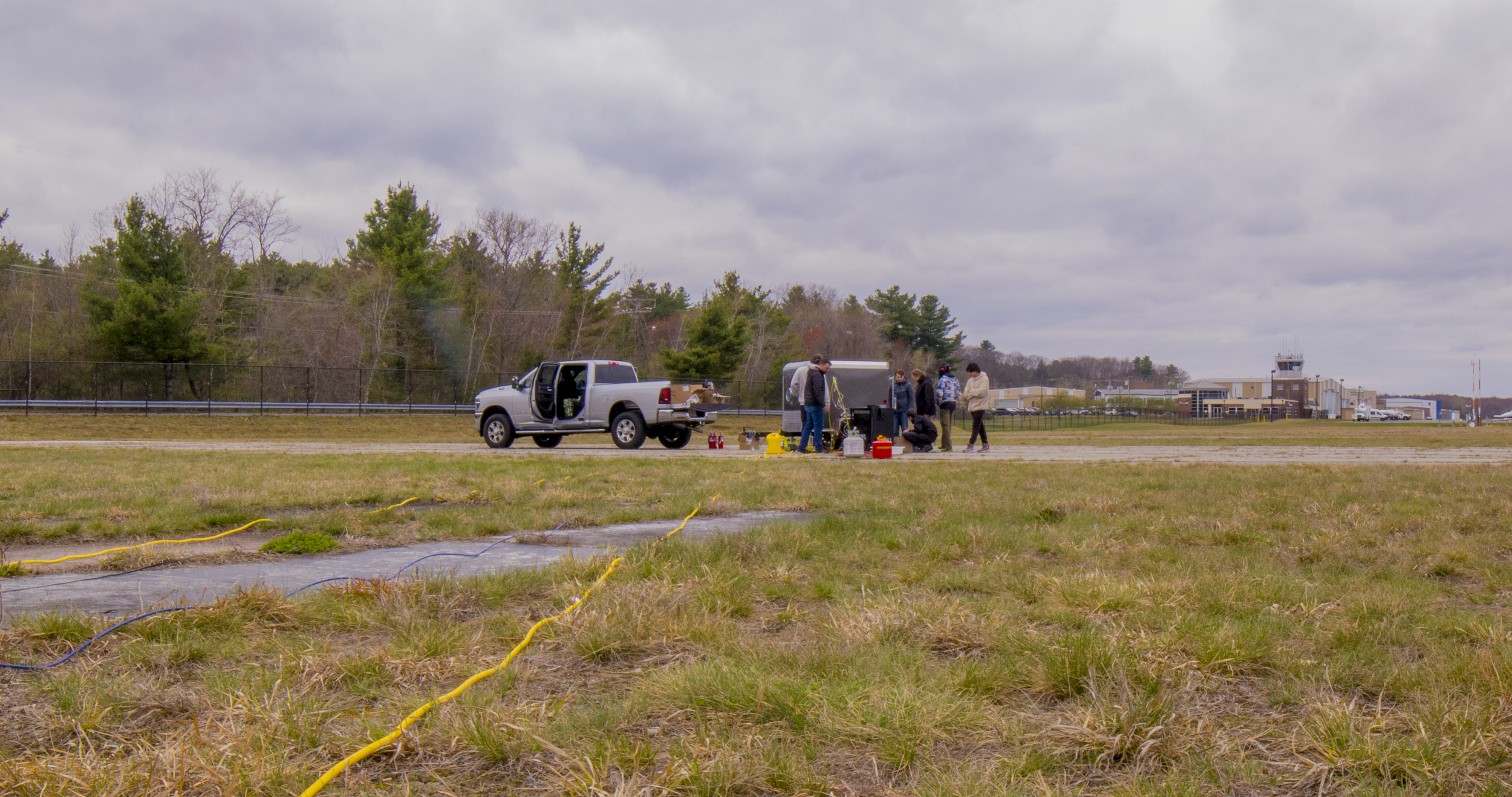
Early in the morning on April 23 we packed everything up and drove to an airfield in Nashua NH for testing. We were accompanied by the entire program staff (professors and grad students) as well as representatives from all the industry sponsors. We were generously given space to setup and test on the airfield by Rotor, an aviation startup headquartered there.
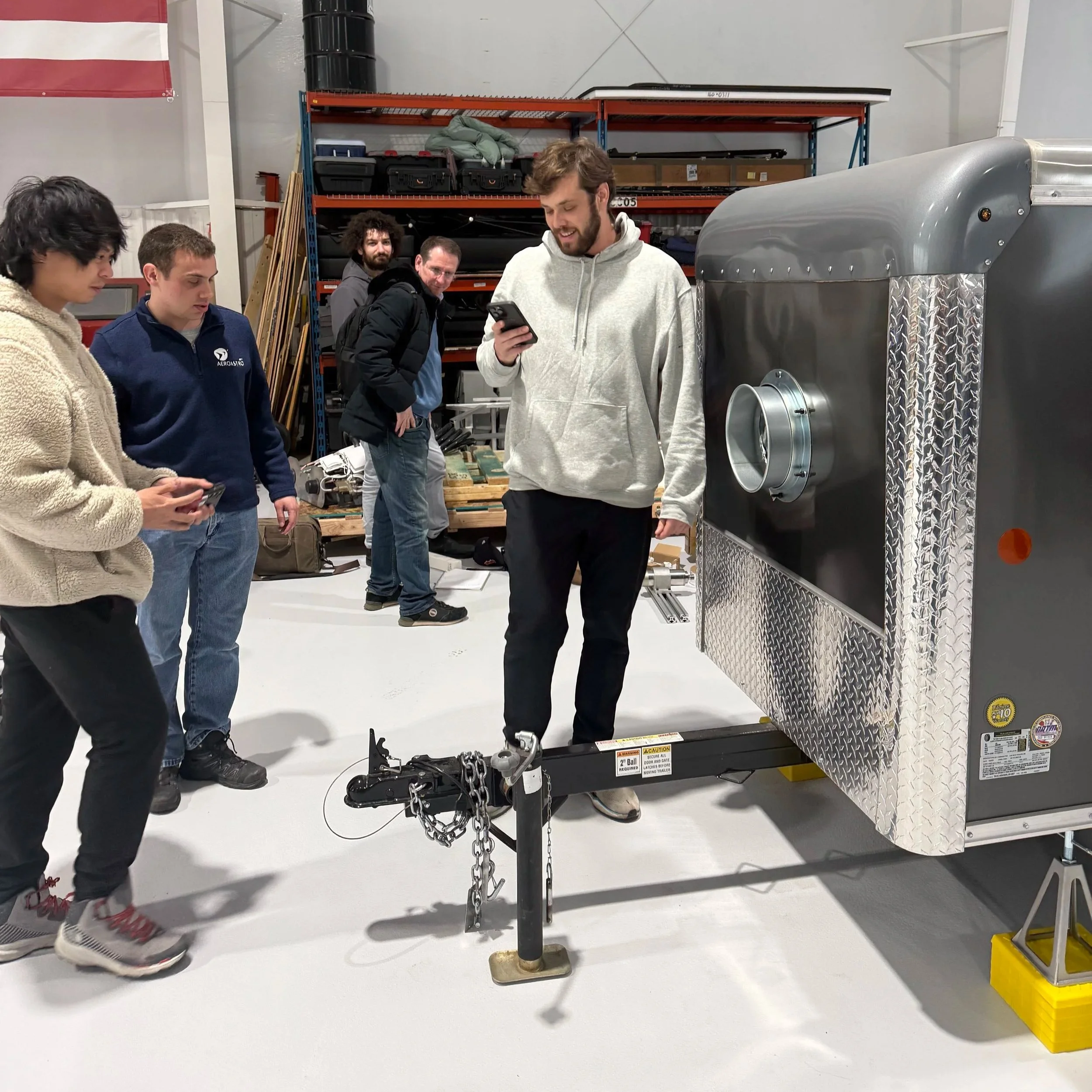
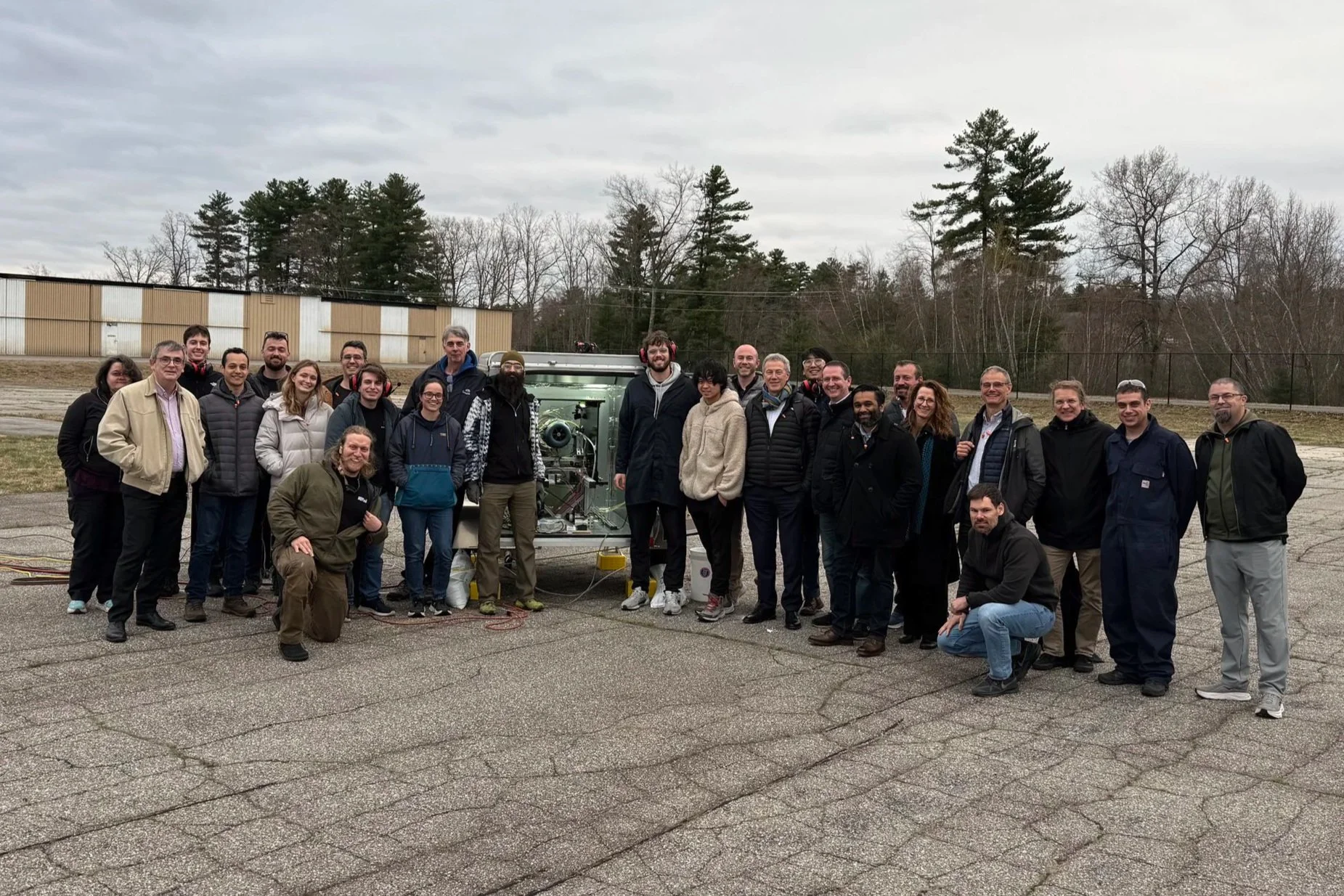
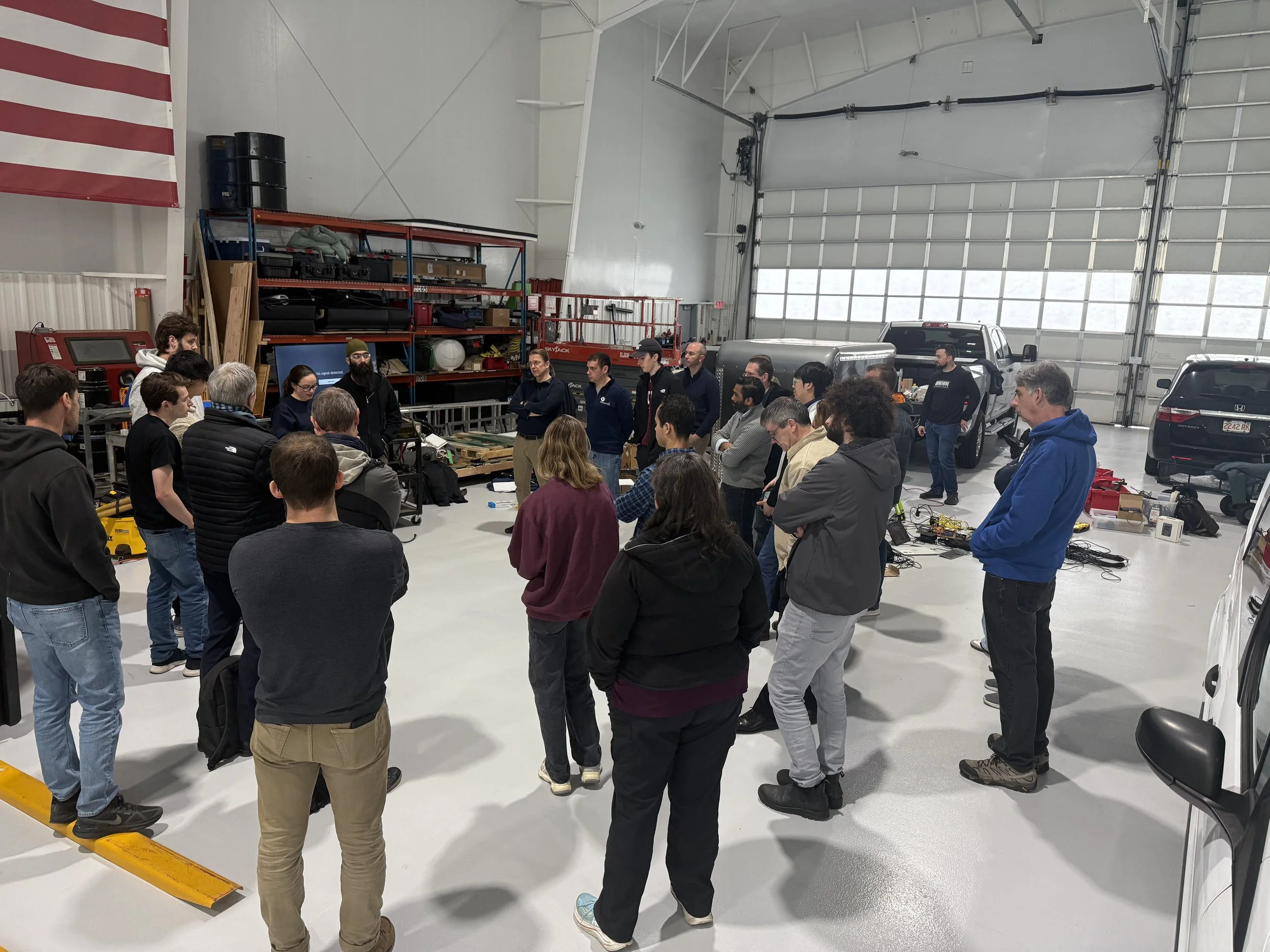
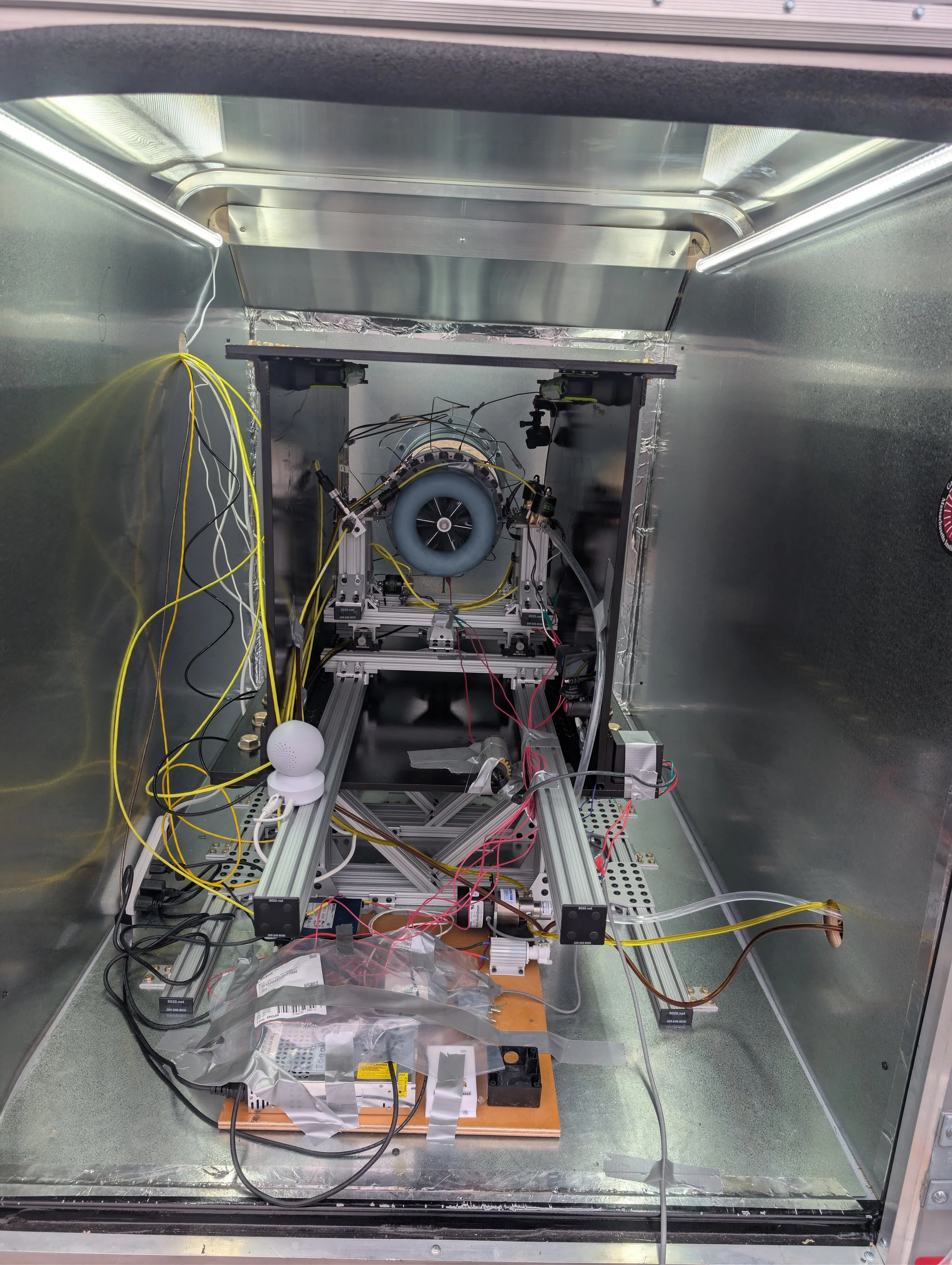
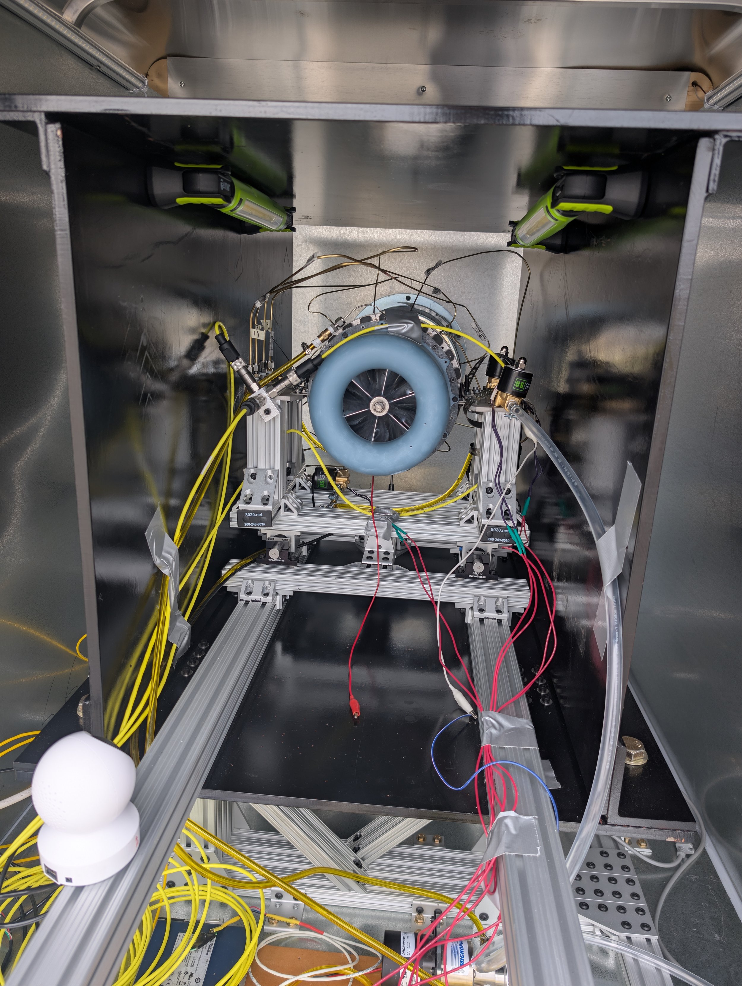
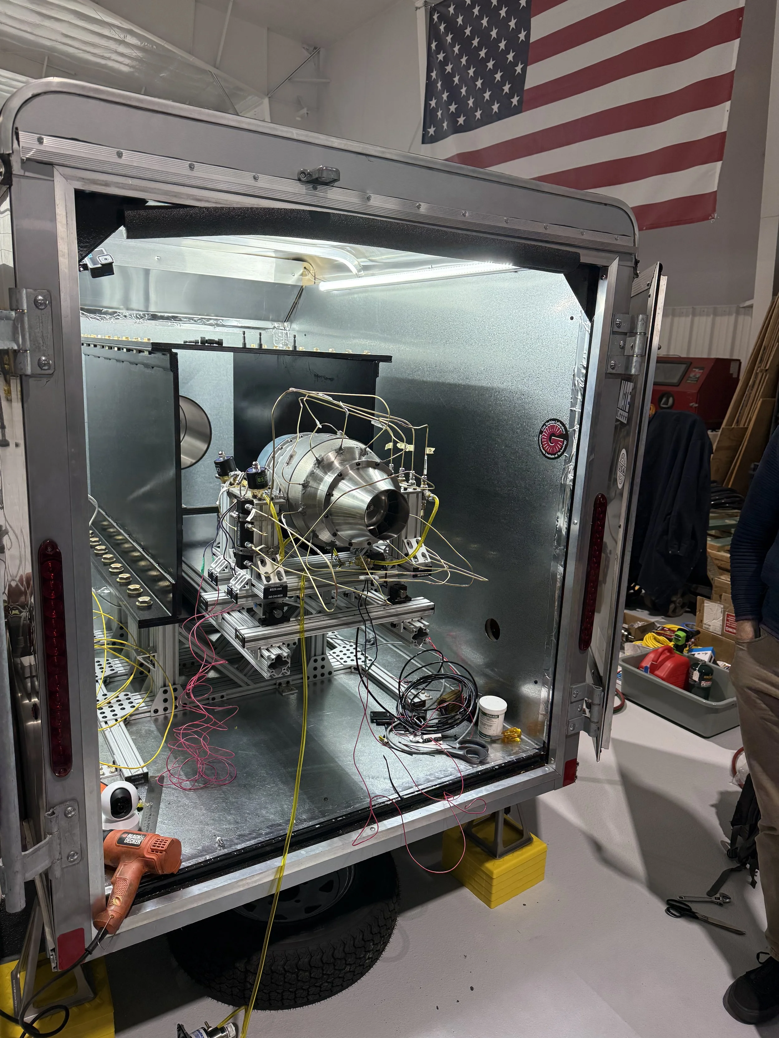
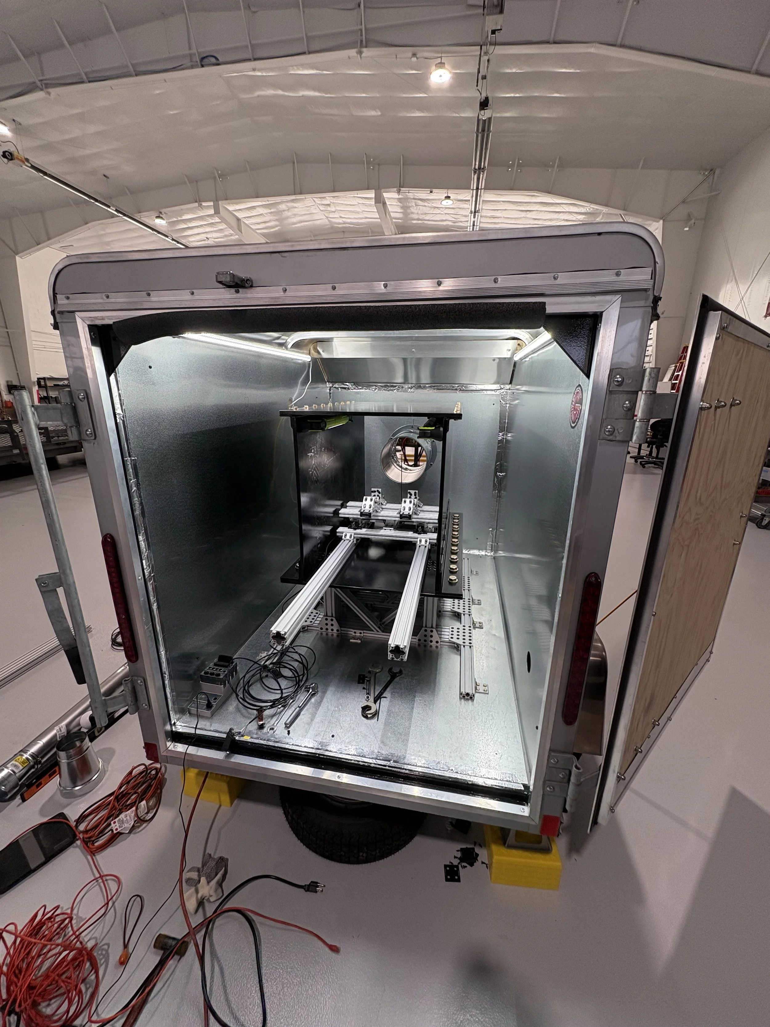
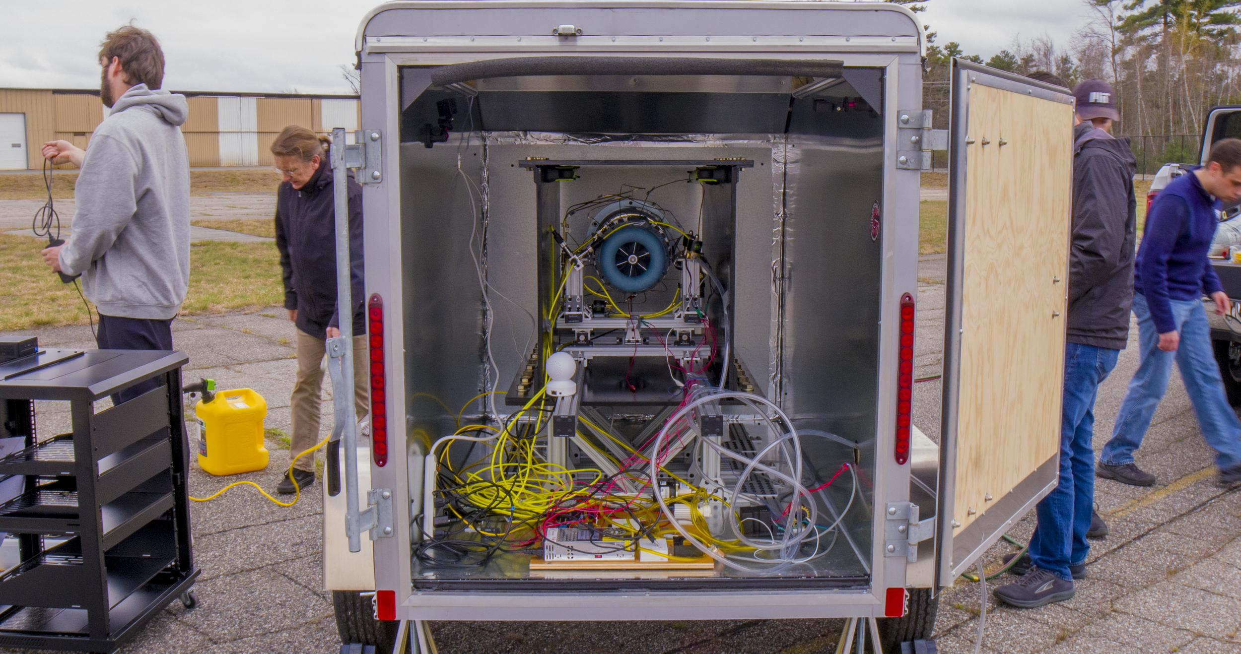
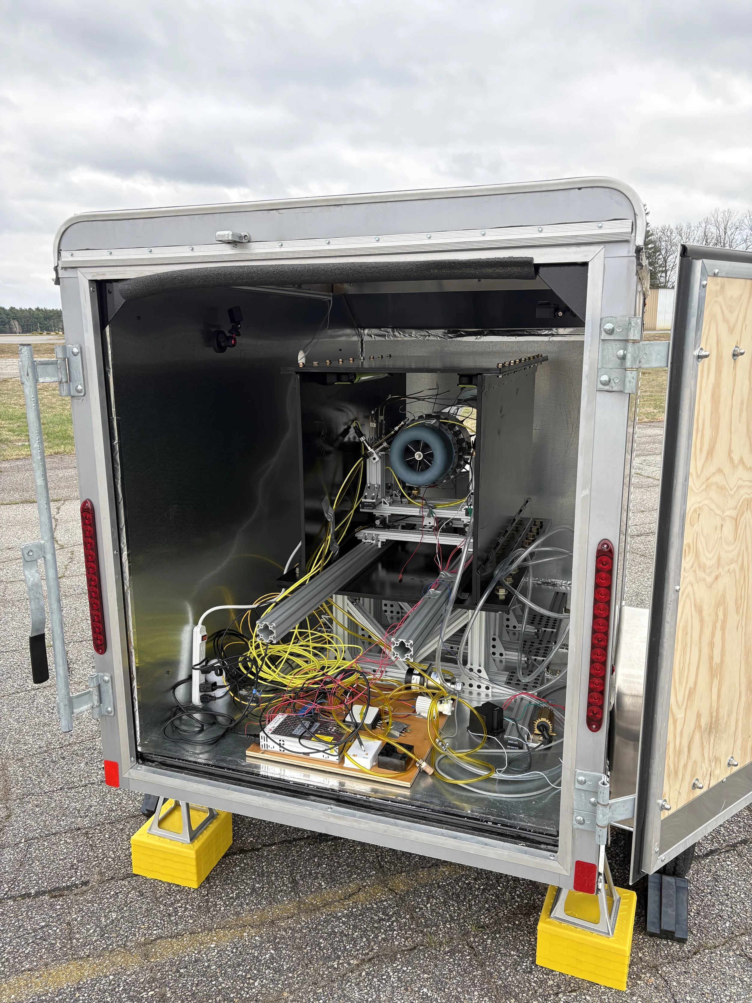
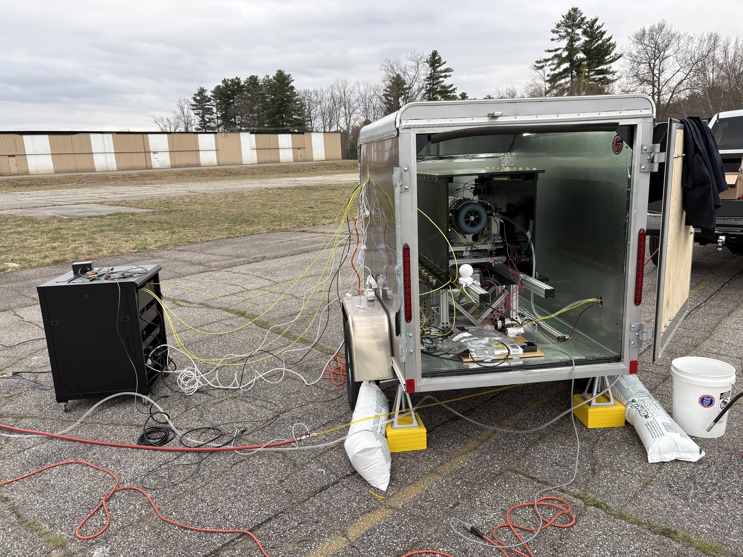
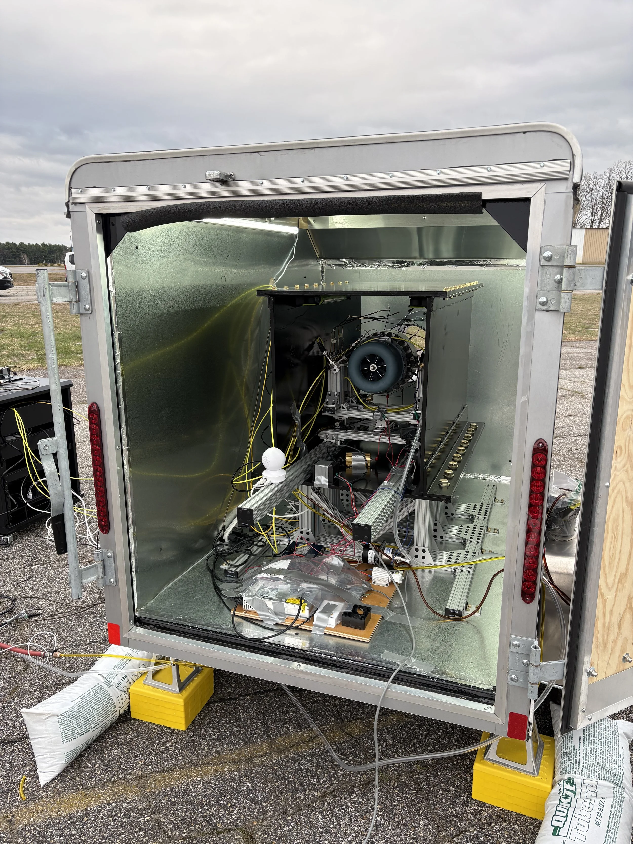
To test our engine, the program staff had built a test stand into a small trailer surrounded by half-inch thick ballistic steel plates.
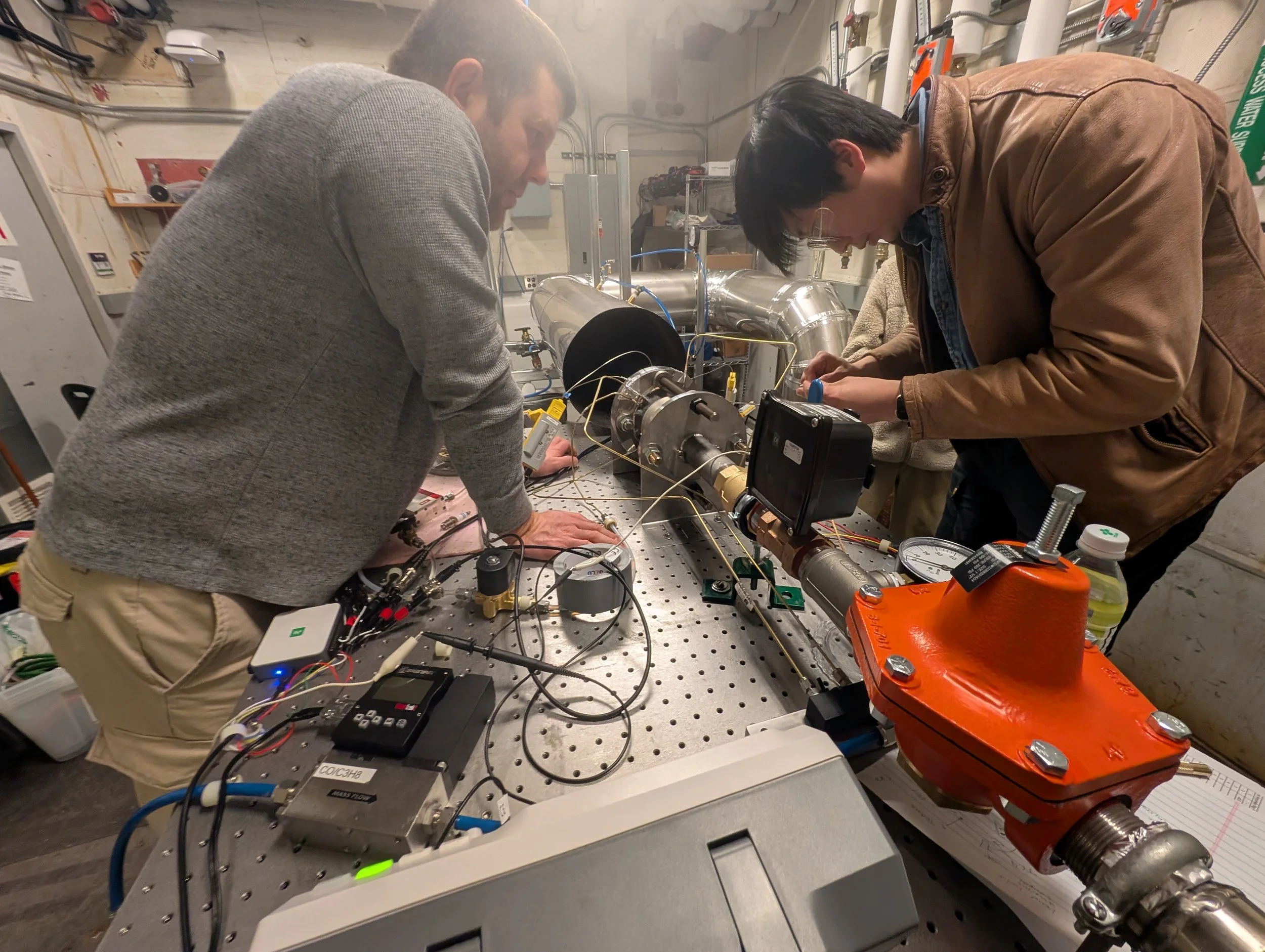
When we arrived, we found out that our fuel lines leading to the engine extended outside of the ballistic shield, so we spent a lot of time bending them to make them fit and hooking up the rest of the sensors and fuel lines.


In our second attempt to try and stop leaks in the fuel manifold, we applied two part high temperature epoxy to all the points where the fuel lines entered the combustor.

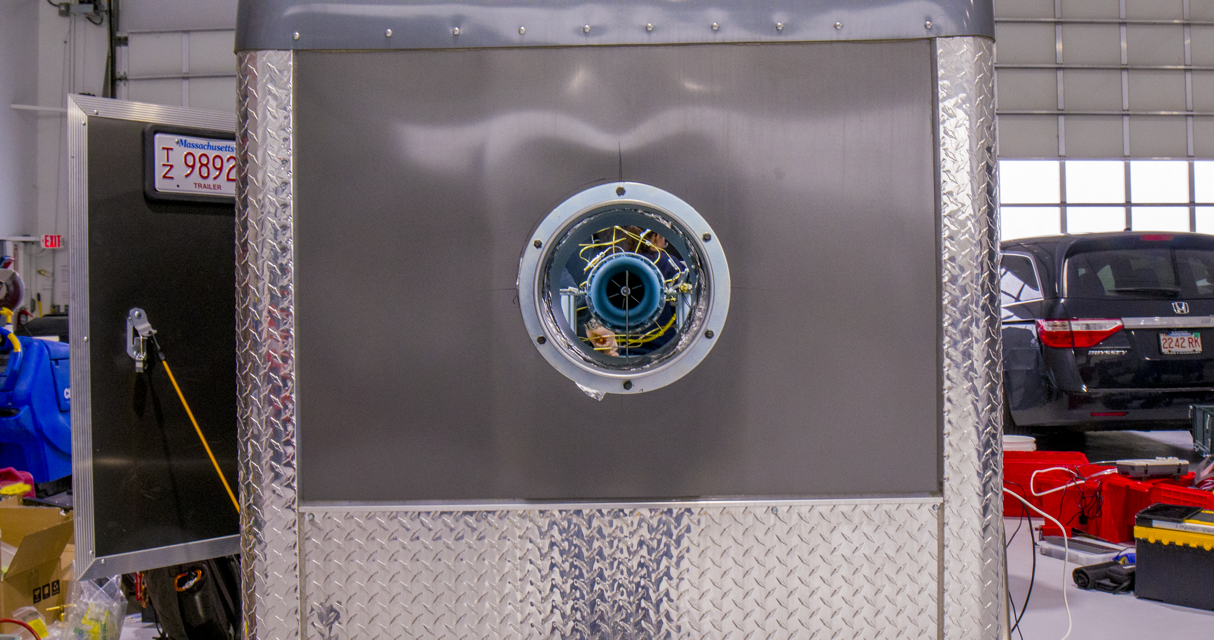
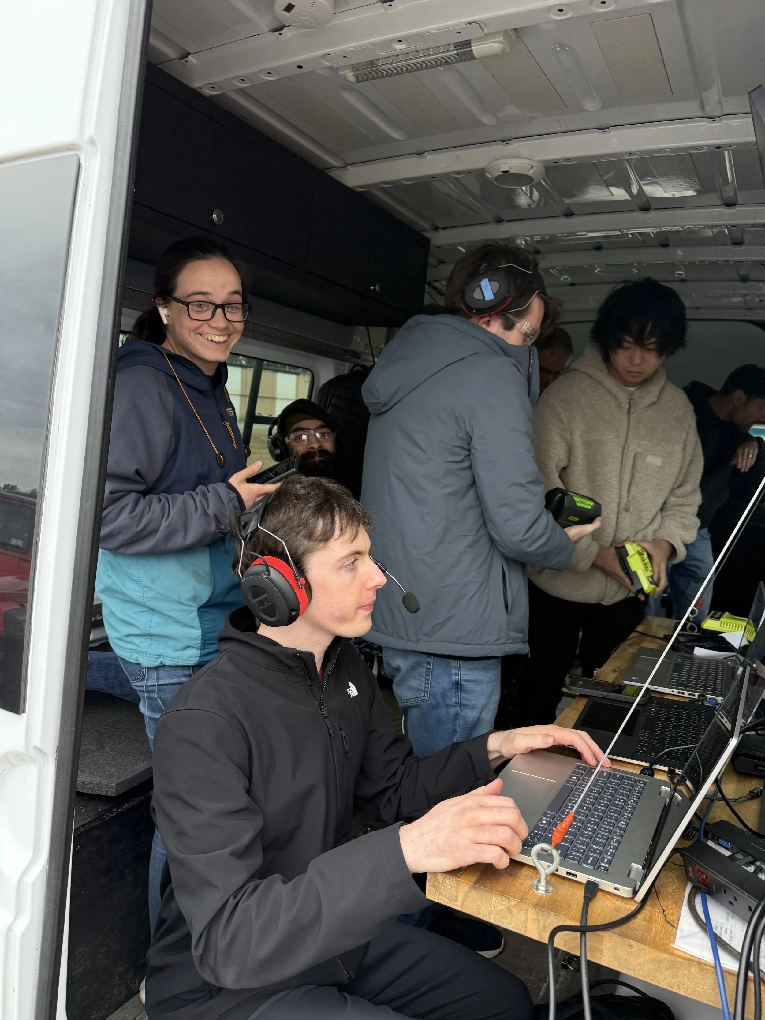
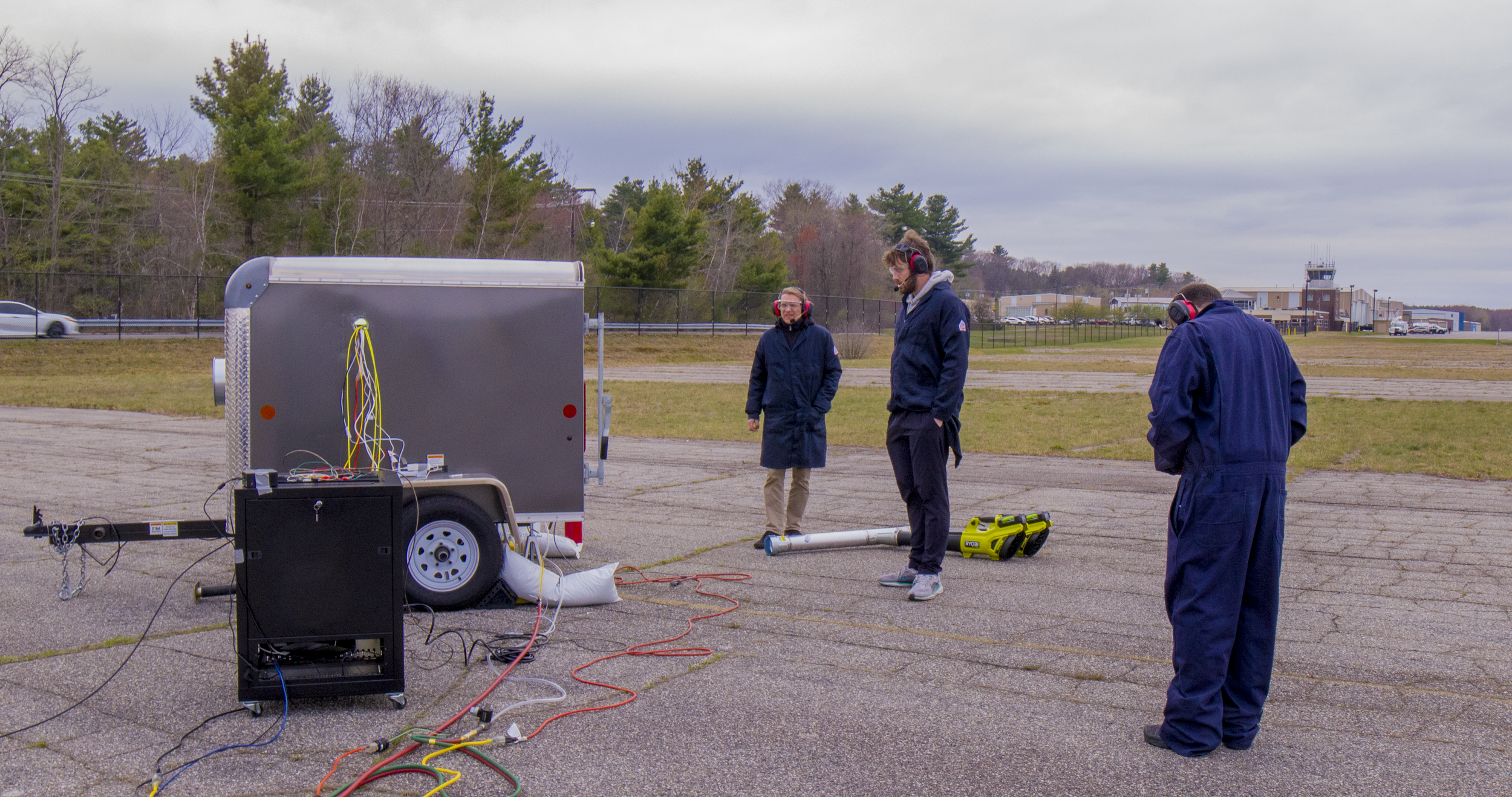
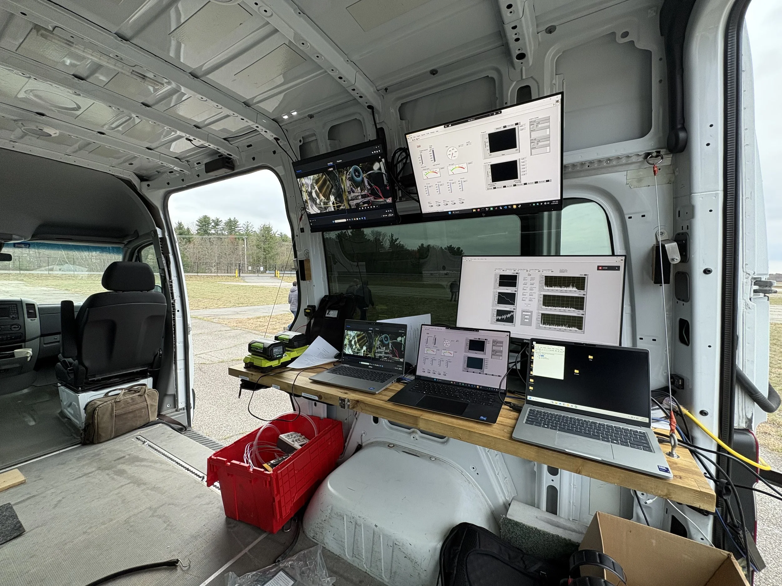
Finally, with the engine fully installed in the trailer, we drove out to the airfield to begin the test. We controlled the engine over an ethernet cable from a van 100ft away, and monitored its performance through a few cameras installed around the trailer. The setup inside the van included LabView readouts of the setpoints commanded to the fuel pumps, temperature and rpm readings as well as the thrust and vibration measurements from load cells and accelerometers in the test stand. To start the engine, a team of 3 people forced air into it via a double-leafblower apparatus and once it was spinning fast enough the operator in the van introduced propane and activated the spark plug.


On our first attempt, it did not ignite, but after that we were able to have two successful runs before our time slot in the airfield ran out and we had to head home. Both times, the engine was able to sustain itself by burning Jet A, with no external air forced in. In the first run we ended up burning quite a lot of oil. It turns out our lubrication pump for the bearings was really oversized, and as our lubrication system was open loop (the oil gets dumped into the exhaust stream after passing through both bearings) a lot of waste oil caught on fire creating a large flame out the back of the trailer, forcing us to cut the test short.
In our second test run, we ran the lubricant pump for short bursts in an attempt to reduce the amount of waste oil in the exhaust. This gave us a chance to run the engine for longer, and we were able to ramp the speed up slightly by increasing the flow of Jet A. We were able to demonstrate the engine idling under its own power and were able to ramp it up enough to produce 3lbs of thrust. This was enough to call our engine design successful but at that point we ran out of testing time, so we were not able to push it to its true operating limits.
CONCLUSION:
I participated in this program because I wanted to get the experience of designing and testing a jet engine. I think they are a unique engineering challenge because of how interconnected all the parts of the system are. It was a fun puzzle to try and reconcile all the competing design requirements and work with a team of similarly talented driven people. I think we could have done significantly better without such a rushed timeline and without trying to shoehorn in AI into a problem it could not really contribute to, but it was a fun experience nonetheless. It is possible that at some point people train an AI that is natively able to understand CAD and CFD simulation but at present all the major models are pretty useless in this domain. The fact that our team prevailed (having the most education in the relevant fields, and the least use of AI) shows the value of human ingenuity and experience when it comes to complex engineering challenges.