STEREOSCOPIC FPV Headset:

These are the goggles that accompany the Stereoscopic FPV Drone (read that first). Since there were no goggles that accomplished the 3D video requirements of this project, I had to reverse engineer two existing headsets and combine them into one solution.
Here are the design requirements for what my headset needed to accomplish:
Display a different signal to each eye (most goggles don’t do this)
Receive video signals on two different frequencies simultaneously (most goggles have only one receiver, and even if they have two, it’s only for redundancy)
All of the other features, like recording the received video signal, taking an HDMI input, and other common features don’t matter for my use case, so I was willing to sacrifice them.
DiagramS:
Here’s the results of the research I did tearing down a pair of goggles and probing various things to determine what I could remove.
Everything with a red X is something I could remove without altering the core functionality for the sake of simplicity and saving space (receiving and displaying a video signal from the drone). Space was at a premium because I was trying to fit two goggles’ worth of guts into one goggle's worth of space.

Here’s the final solution:
Blue arrows are all the wiring I had to do to graft my own electronics onto the two mainboards.

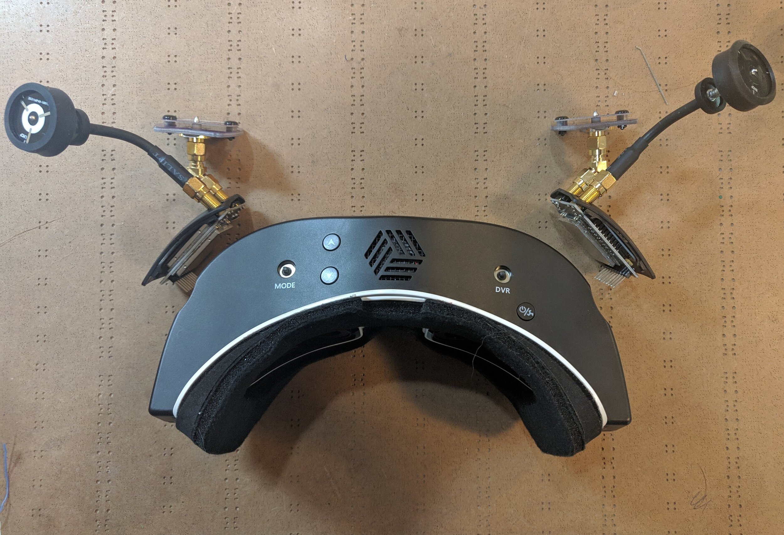
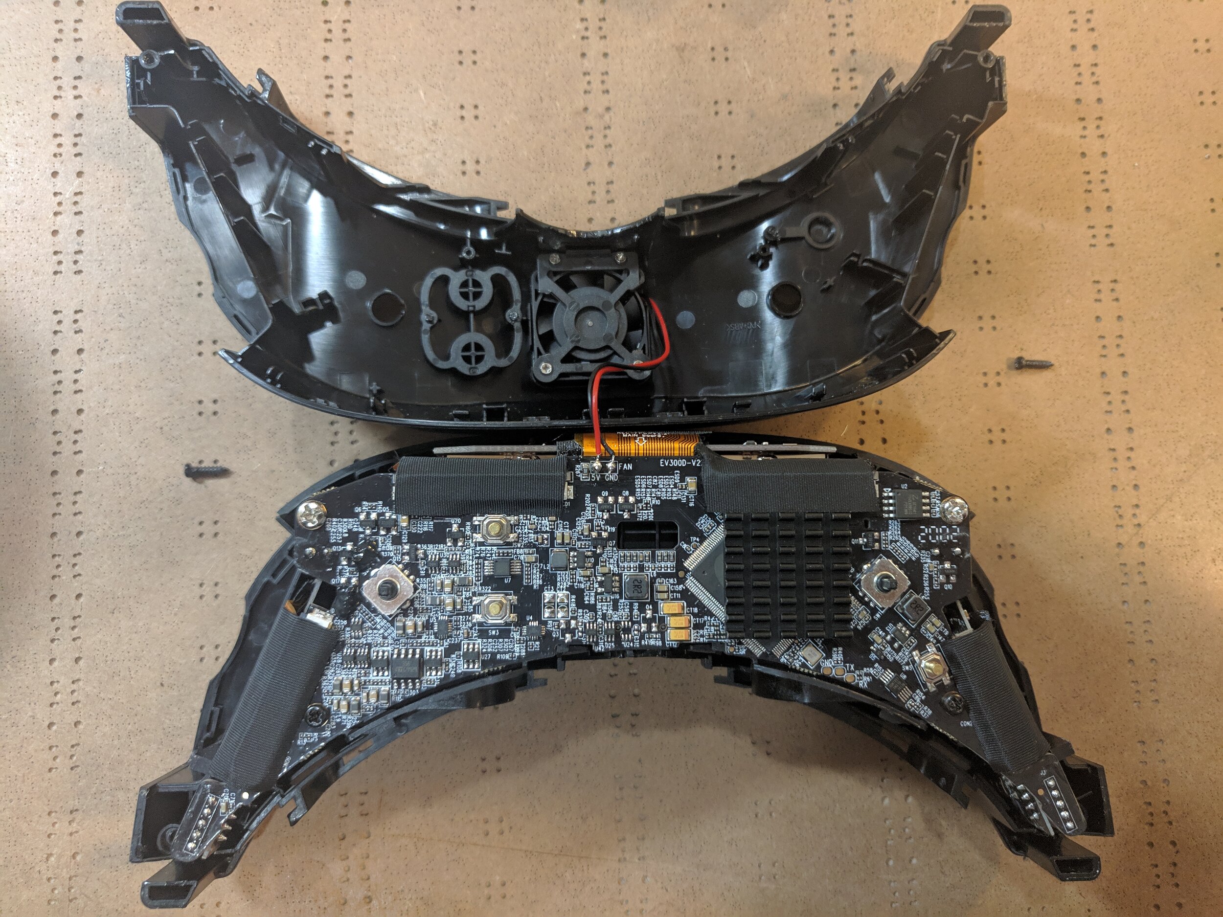
Original GoggleS Teardown:
I started by tearing apart an existing headset, the Eachine EV300D. I selected this one because they have two receivers, meaning I would not have to modify them to hold a second one. Unfortunately, these goggles keep the receivers tuned to the same frequency, and simply choose the one with the better signal to display to the user. The goggles also have one screen per eye, but the mainboard sends the same video signal to both screenes.
This means that, in order to receive two different signals and show one to each eye, I needed the mainboard from a second pair of goggles. This way, one mainboard would handle each video signal, and I would have to fit both of them inside the shell of one headset.
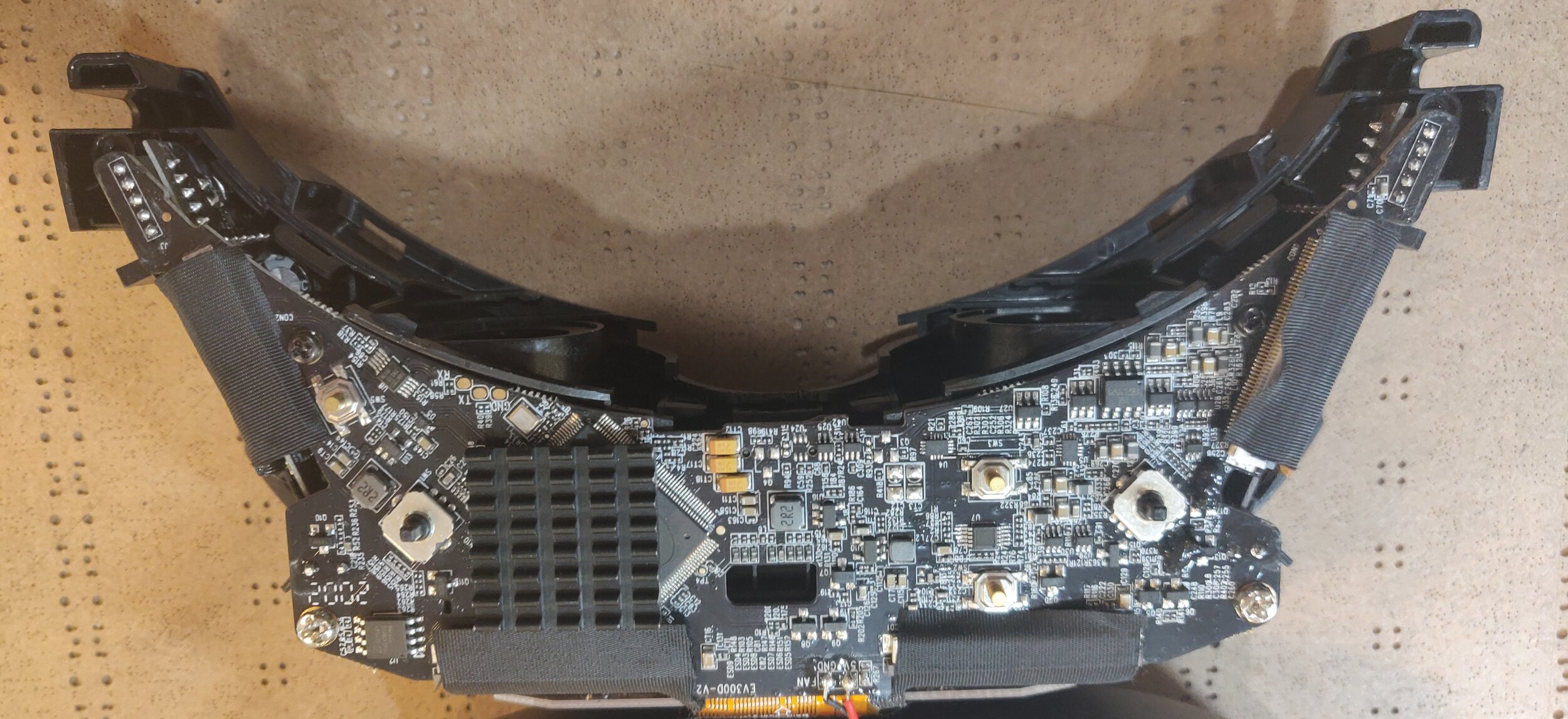
I disassembled the entire thing, and analyzed each circuit board. I got lucky, in that the goggles were able to display a video signal even when only one screen and one receiver were connected.
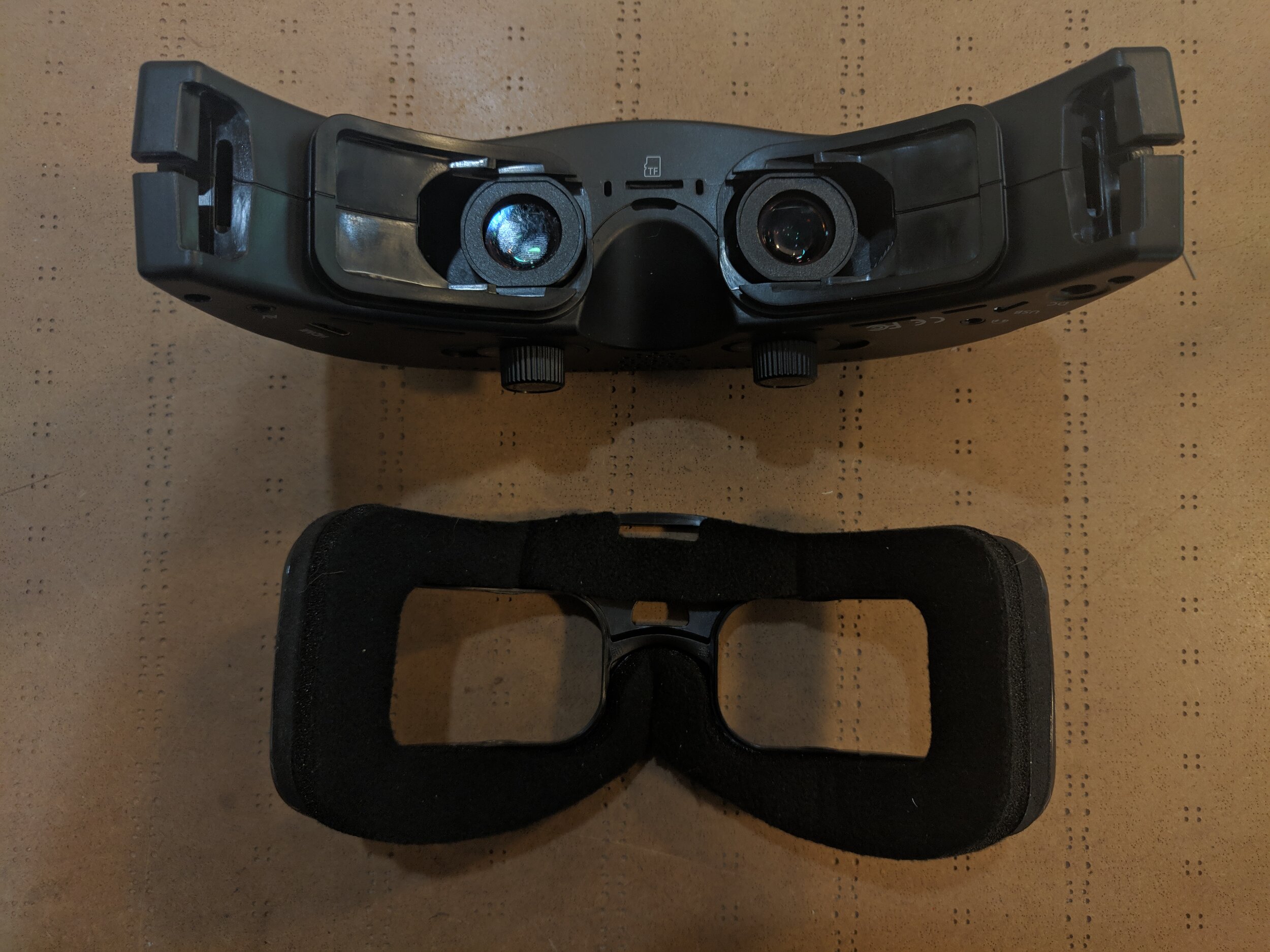
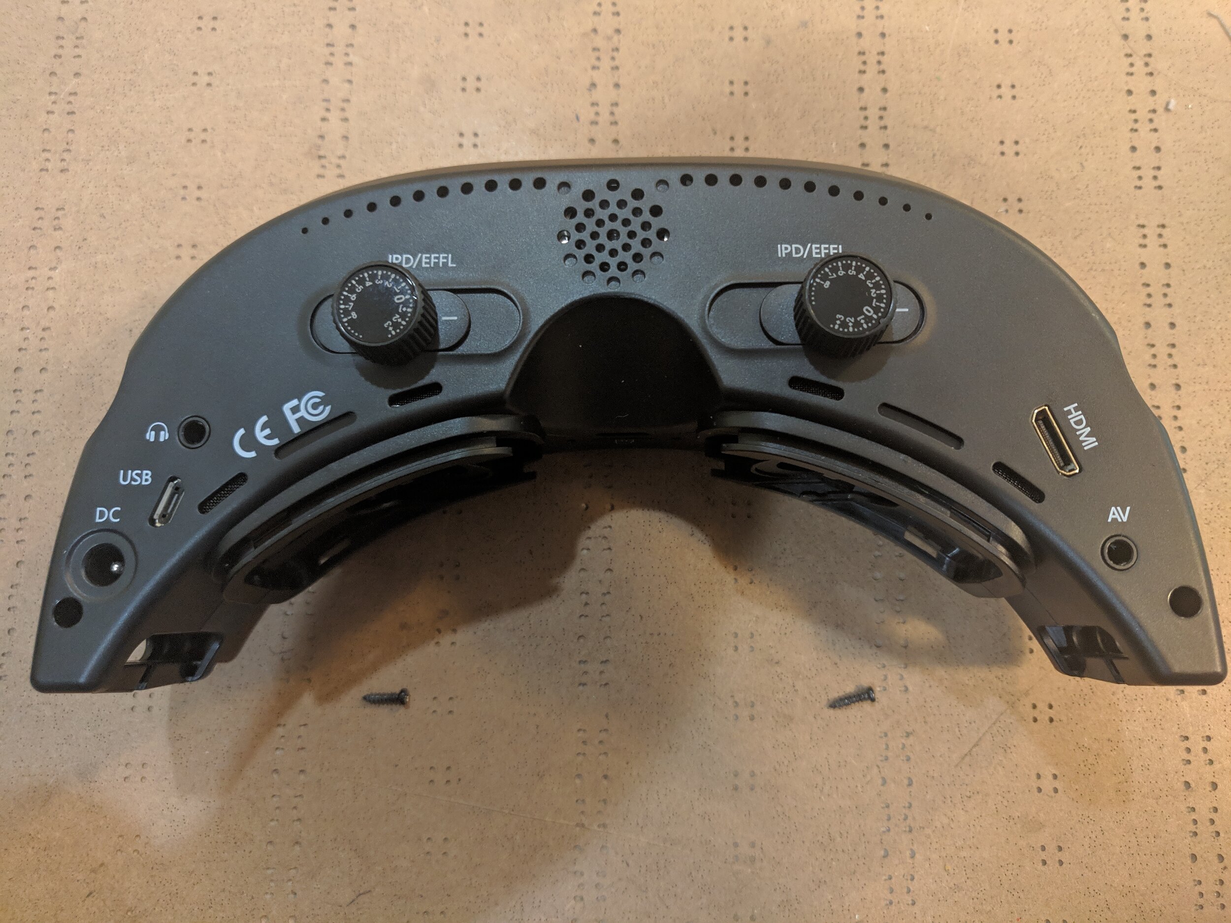
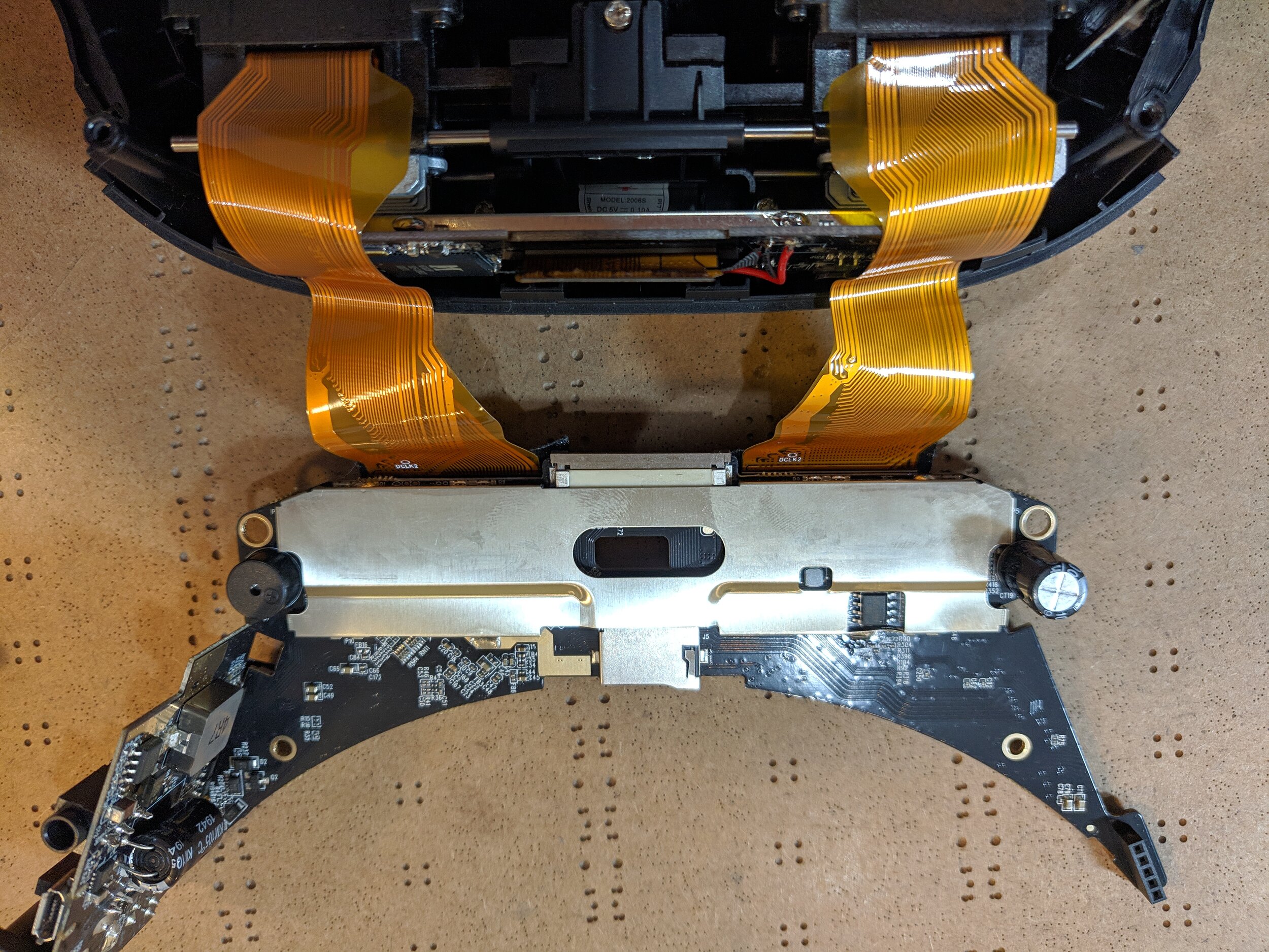
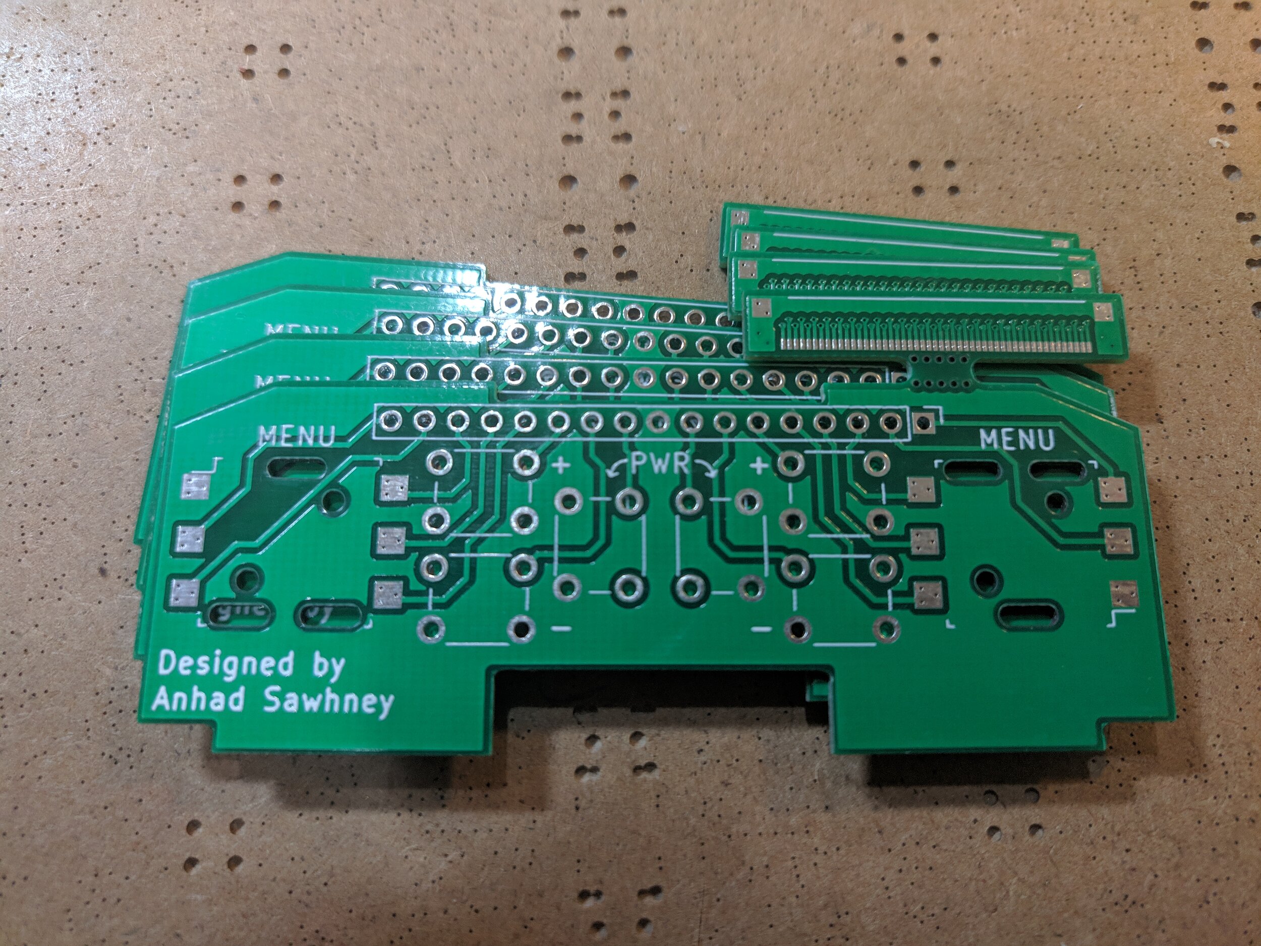
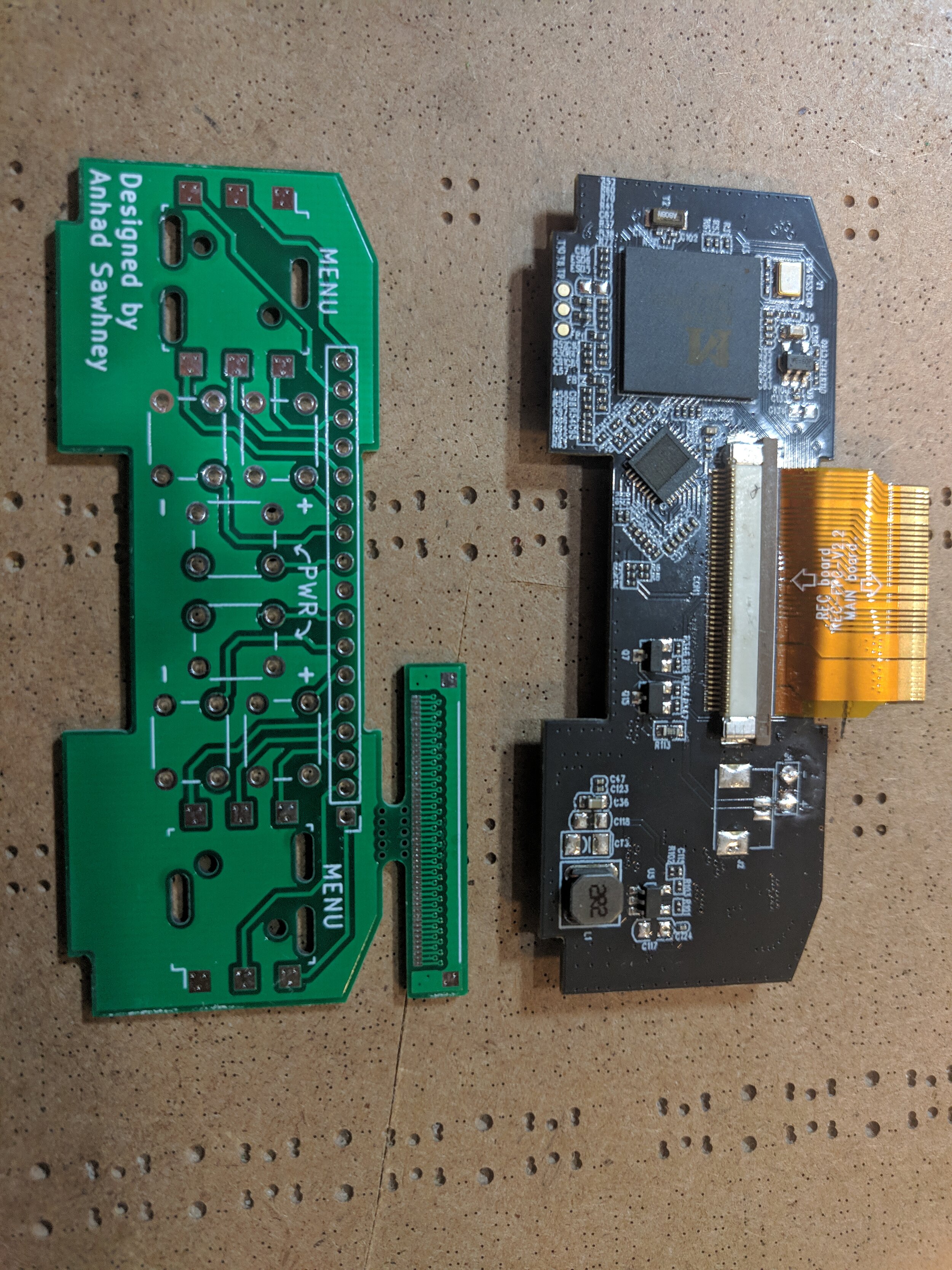
Replacing the FRont Panel PCB:
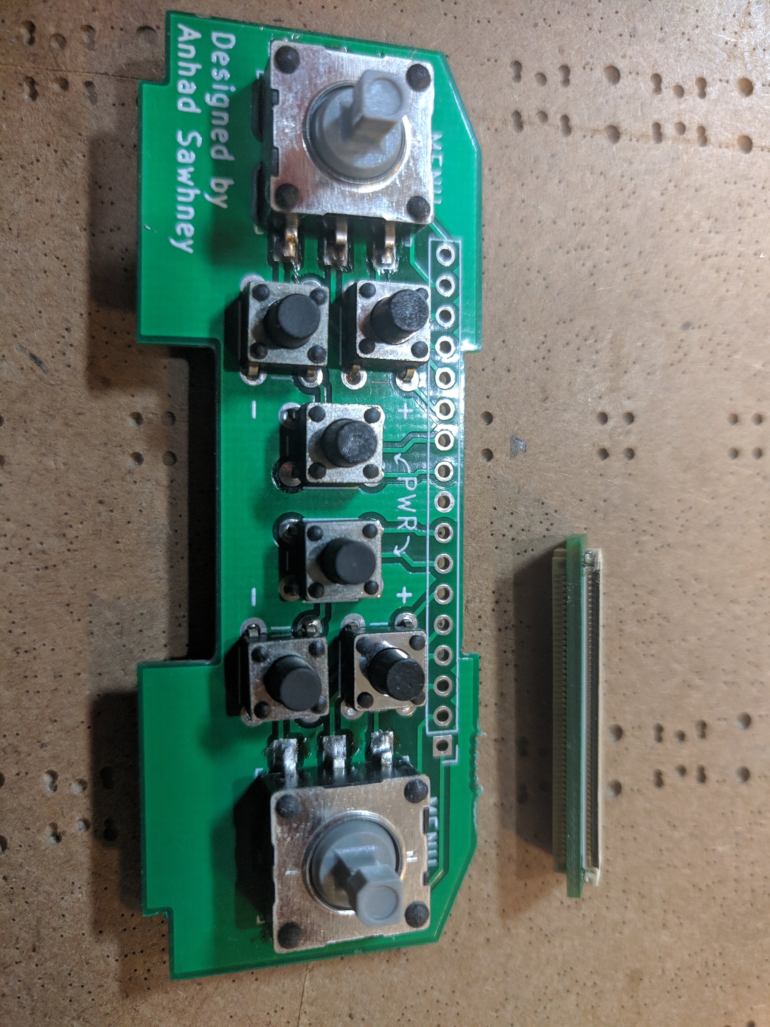
The best way to fit the mainboards inside the goggles was to stack them, thus only slightly increasing the total height of the goggles. However, this meant that the buttons on the bottom mainboard would be covered up. So, I made a custom circuit board to move the buttons from both mainboards to the front of the goggles, instead of the top. After cracking the goggles open, I discovered that there was already a board in the front, which would be an ideal candidate for replacement. This mainboard turned out to only be used for recording the video received by the goggles to an SD card. I opted to remove this functionality and replaced it with my own board.
GOGGLE ELECTRONICS MoDiFications:
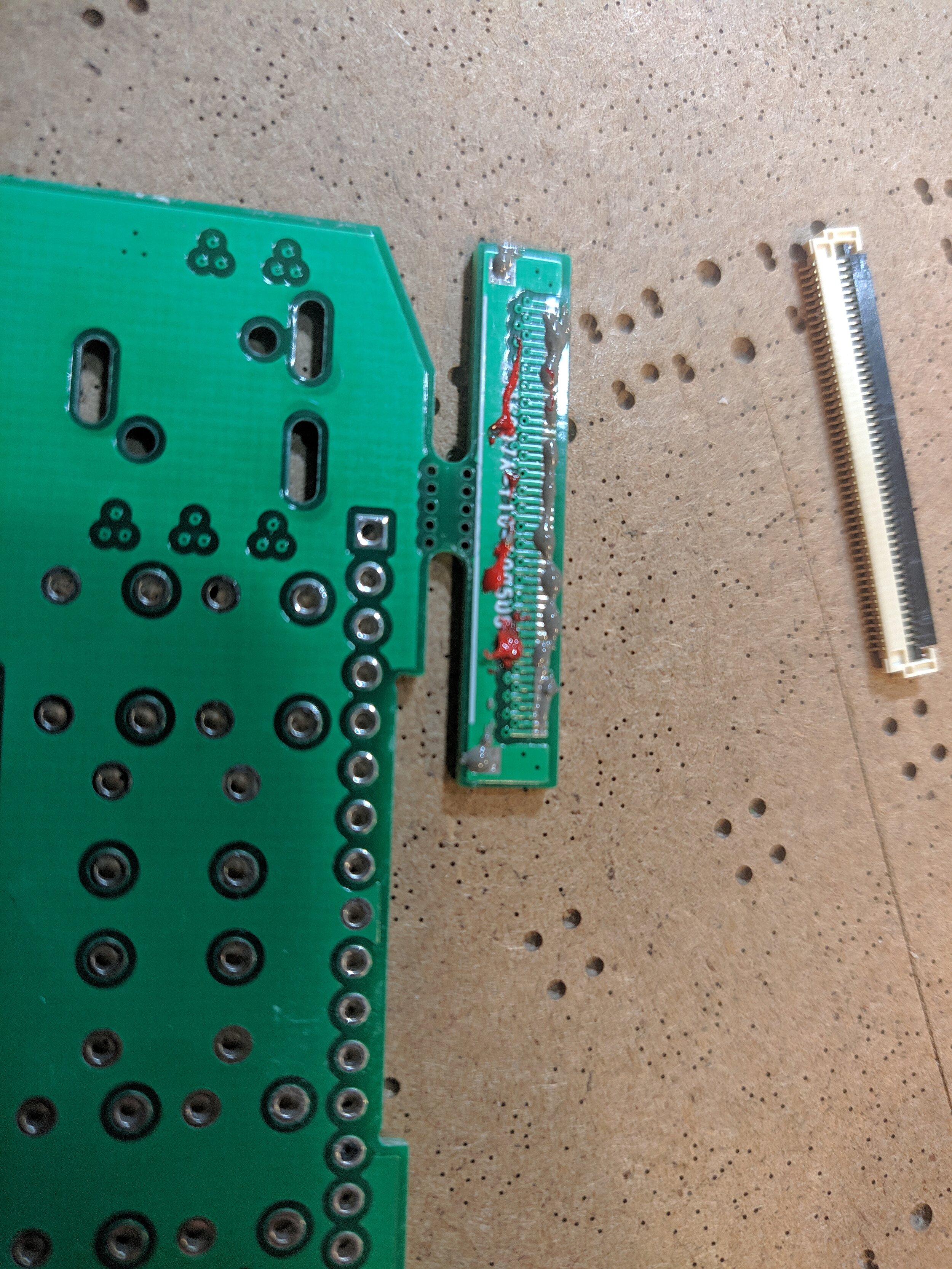
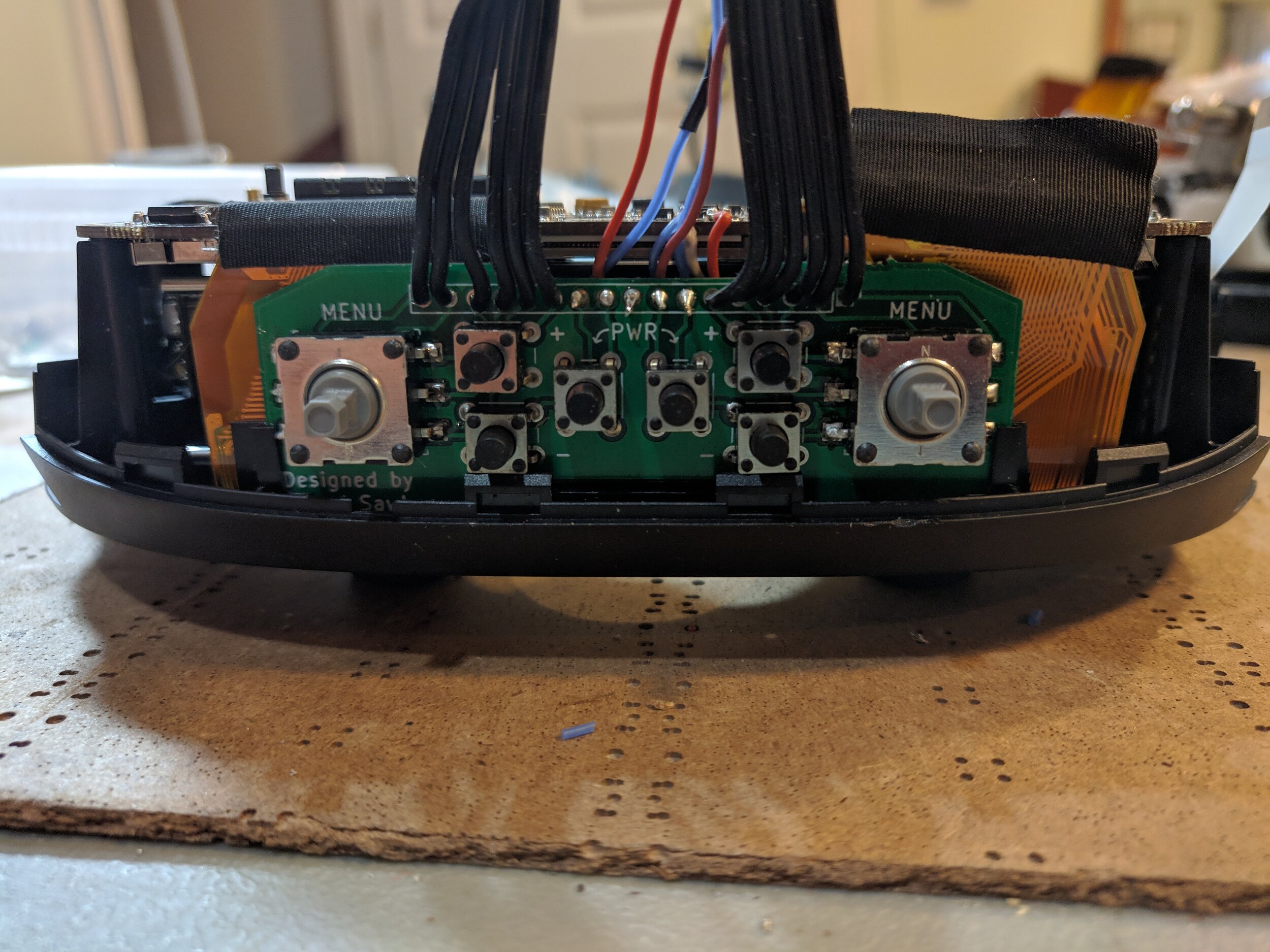
The most complex part of this project was modifying the circuit boards for both goggles. I had to extend the cable to one of the receivers to reach all the way to the top board in the stack. I also had to solder wires to the existing locations of the buttons in order to transfer them to my circuit board.
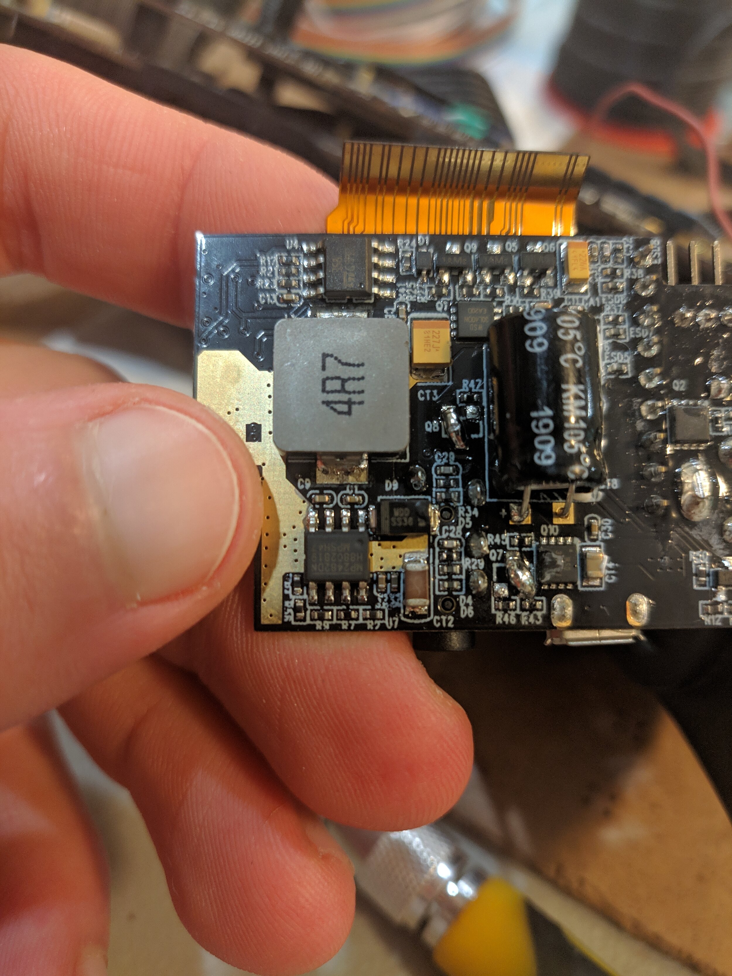
I also had to figure out how to get power to both boards. The power supply board doubled as the socket for one of the receivers, and I did not have space to fit a second one in the goggles. So, instead I found the connector that carried power between the power supply board and the mainboard. I then duplicated these connections for the top mainboard.
The first time when I powered everything up, one board started beeping incessantly. It seemed as if it was complaining about a low battery, even though the battery was full and it was receiving all the power it needed. I did some probing, and it turned out that one last connection needed to be made to both boards. The goggles used one pin in the ribbon cable that went to the right video receiver to sense the battery voltage. I carried this connection over to the top board as well and it stopped complaining. (This was done using the blue wire that is visible in the last two pictures)


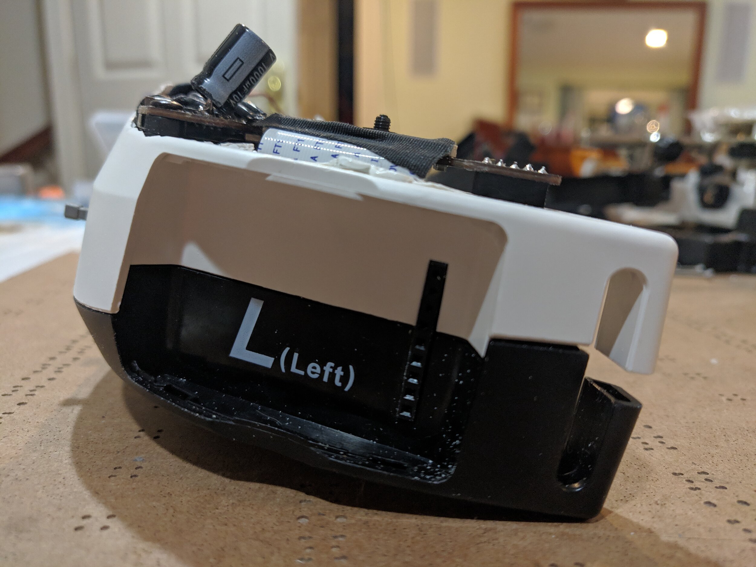
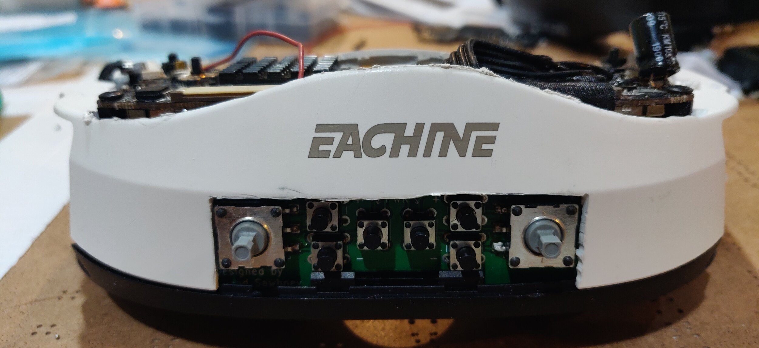
Cutting the Top Piece To fit the modifications:
The final step in the modification was to get everything to fit back into the plastic shell. This involved cutting away a significant portion of the top piece until everything fit together. I did a first test run using the sacrificial white plastic piece from the first pair of goggles. I ended up cutting away too much plastic, but determined exactly what needed to be removed for the second try.
I did the final cut in the black plastic piece, removing the bare minimum required to make the second board fit, and trying to maintain the structural integrity of the goggles. I also left a space for the fans to be mounted to the goggles, to make sure that the bottom board received fresh air and didn’t overheat.